


Simple StackShot Controller
Description
The development of Simple Stackshot Controller has been made to answer a personal need : I needed to control the positionning of a camera in relation with the DOF of the previous positionning of the rail.
Moreover, as there is currently no simple software Stackshot controller available, I decided to create my own version showing the same capabilities of the hardware one.
As a computer screen provides more comfort compared to a 4-lines LCD, and, as many people are creating their stacks indoors, I think that some people could be interested to define their sequences in a simple and intuitive way and will be happy to be abble to adjust, later, these settings at will.
The result is a piece of Software, that should been interesting to all existing users of the rail. With 3 main orientations :
- Classic users : You can do 7/7 of what the hardware controler can do.
- Some users : You can use the mega special combo sequence “Adaptive Bellows” which allows the rail to dynamicaly calulate it’s position based on the characteristics of the camera and the lens and on the subject distance. This mega special combo is described in its dedicaced chapter bellow.
- Other users : You can use the “Adaptive Bellows” mode with a virtual rail. This combination allows you to have under the eyes the results of your Sensor, Lens and Bellows Extension.
Installation
Just download the archive corresponding to your system, decompress it where you want and launch the software.
Getting Started
If a Stackshot Rail is connected on a USB Port, and if it is powered, you’ll see the following window :
If you see this then you can proceed to the next chapter.
Documentation
Main Window
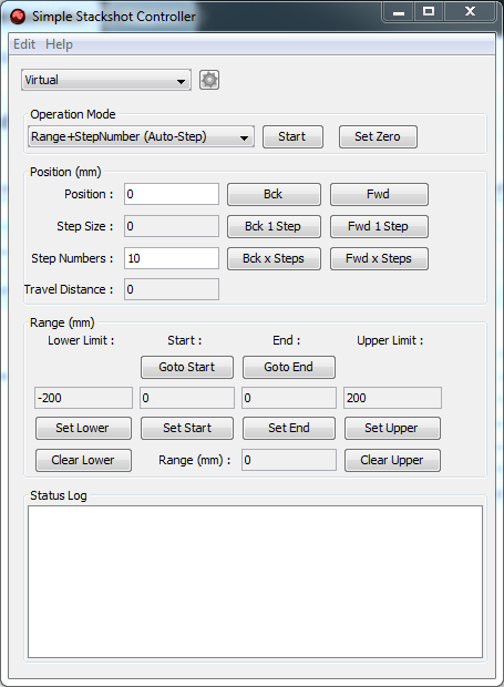
Here is the main window :
This window is composed of 5 groups :
- Rail Selection
- Operation Mode
- Position
- Range
- Status Log
Rail Selection
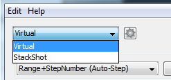
This Combobox allows you to select the StackShot Rail or a Virtual Rail.
When a rail is selected you can click on the config button on the right to configure it :
Stackshot Rail configuration

Look at your Stackshot documentation. These parameters are the same.
Virtual Rail configuration

Operation Mode Group
In this group you’ll find :
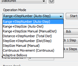
- Operation Mode ComboBox : You can select there which mode you want to use. The first 7 are exactly the sames as those that you’ll find on the hardware Stackshot controller. The last one is a special mode which is described in its dedicaced chapter bellow.
- Start Button : This button has to be used to launch a sequence
 . When your using a non ranged sequence, this button is replaced by 2 Start Buttons
  (allowing you to choose the direction of the rail movement).
 - Pause Button : When a sequence is running, the Start Button is replaced by a Pause Button
 . Pushing it has the effect of completing the current step and then to wait until the user choose to continue the sequence.
 - Restart Button : When a sequence is paused, the Start Button is replaced by a Restart Button
 . Pushing it has the effect of restarting and continuing the sequence.
 - Cancel Button : There is not just one Cancel Button…
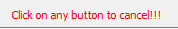 In fact all buttons (except the Start/Pause/Restart) are able to cancel a sequence or a move. You always able to abort any move or sequence by pushing any button on the hardware controller.
 - Set Zero Button : This button sets the current rail position as the 0 reference and recalculate all absolute position values (Lower and Upper Limit, Range Start and Range End, and other ones in the Adaptive Bellows Workflow).
Position Group
This group can be considered like the transporter part.

Field Position is always editable. Fields Step Size, Step Number and Travel Distance can be editable or not, based on the Operation Mode selected.
- Position Textfield : There you can type the value of a position where you want to move the rail. If the value given is outside the Lower or Upper Limits (see later), the target position is set to the limit.
- Step Size, Step Number, Travel Distance Textfields : When these values have a meaning for the Stackshot hardware controller, then they have the same meaning here. When they have no meaning (Adaptive Bellows), you can use them as you want.
- Bck and Fwd Buttons : When you click on them the rail move in the selected direction until you release the button.
- Bck 1 Step and Fwd 1 Step Buttons : When you click on them the rail moves of one Step Size distance in the selected direction.
- Bck x Steps and Fwd x Steps Buttons : When you click on them the rail moves of Step Number x Step Size distance in the selected direction.
Range Group
This group allows you to set up the safety limits and the range of your ranged sequences.
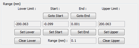
- Set Lower and Set Upper Buttons : When clicked, these buttons get the current position and set it as a safety limit. e.g. : if Lower Limit is set to -10mm, the rail will never be able to go lower than -10mm.
- Clear Lower and Clear Upper Buttons : When clicked these buttons free the safety limit selected and set them to, respectively, -200mm and +200mm.
- Set Start and Set End Buttons : When clicked, these buttons get the current position and set it as the start or as the end of the range. this range has to be define for the ranged and for the Adaptive Bellows sequences.
- Goto Start and Goto End : When clicked the rail moves to the start or to the end of de defined range.
Status Log Group
Well,… it’s there that you can see what’s happening.

Colors Meaning
Sometimes, somes fields change colors allowing you to detect problems :
Ranged Modes : If Range Start (or even Range End) is bellow Lower Limit then these fields became red. If Range End (or Range Start) is above Upper Limit then these fields became red.
Non Ranged Modes : If current Position added or lowered with Distance is above Upper Limit or bellow Lower Limit then these fields became red.
In these cases, the rail will never move beyond the safety limits (Lower and Upper Limits). When you’ll start you’re sequence, this one will begin, and will end at the safety limit.
Adaptive Bellows Mode : If Upper Limit is above the calculated Infinite Position then these fields became blue. In the case, the calculated Infinite Position is the real upper safety limit.
Adaptive Bellows Workflow
Here is the Adaptive Bellows Workflow window :
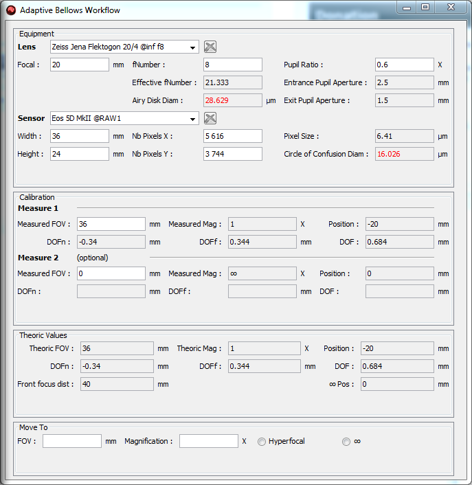
The purpose of this mode is to automate the creation of stack with pictures ranging from macro field of view to landscape field of view. This is done in a particular bellows configuration :The lens is static and the camera is moving. The idea to create a Stackshot mode for this specific need came from this post on www.photomacrography.net.
The best way to begin with this mode is to walk along the following workflow :
Define your Lens
To caracterise a lens your just need to know its Focal Distance, its fNumber and eventually it’s Pupil Ratio.
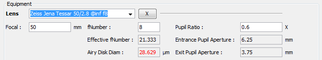
- Focal Lens field : If your lens is focused on infinity, then the official Focal Distance is what you need to use. If your lens is not focused on infinity then its focal distance is surely lower than the official value. In this case you can use the official value in a first step. The following calibration process will allow you to calculate the real Focal Distance.
- fNumber : Just use the fNumber that you set up on your lens.
- Pupil Ratio : This value corresponds to the ratio between the exit and the entrance Pupils. This ratio is used to calculate the DOF and has some impact on near focusing calculations. If you can’t measure it, just use the value 1. In this case, the DOF calculated may not be realistic but should be sufficient if you play with the DOF Overlap ratio (in Preferences).
The Effective fNumber corresponds to the apparent aperture as seen at the sensor plane. The Effective fNumber is dynamicaly calculated with the fNumber, the Pupil Ratio and the Magnification. (Magnification is based on the calibration and the rail position – see later).
The Airy Disk Diam corresponds to the smallest disk an entering ray of light would produce on the sensor. This is a representation of the diffraction. This disk is dynamicaly calculated with the Effective fNumber. If the value is red, it means that the Airy Disk is greater than the minimal Circle of Confusion and that you have a lose of resolution due to diffraction.
You can save your Lens by typing a name in the combobox and hitting ENTER. You can delete a Lens by clicking on the X Button. You can edit a Lens by selecting it in the combobox, then after values edition, select the combobox textfield and hit ENTER.
Define your Sensor
To caracterise a sensor you need to know it’s size (in mm) and it’s pixel numbers.
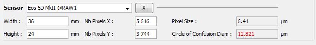
- Width and Height : You just have to type the official size of your sensor (look at your camera documentation).
- Nb Pixels X and Nb Pixels Y : You just have to type the official pixels number of your sensor (loot at your camera doc or at the number of pixels of a picture generated by your camera).
Pixel Size is simply the result of the ratio between Width and Nb Pixels X. The Height and Nb Pixel Y values are not used.
Circle of Confusion Diam corresponds to the maximum size of a blurred point able to resolve to a pixel. This value is the Pixel Size multiplicated by the Max Circle of Confusion (x) ratio found in the Preference window. The ratio is sensor dependent. If theCircle of Confusion Diam value is red, it means that the Airy Disk is greater than the Circle of Confusion and that you have a lose of resolution due to diffraction.
You can save your Sensor by typing a name in the combobox and hitting ENTER. You can delete a Sensor by clicking on the X Button. You can edit a Sensor by selecting it in the combobox, then after values edition, select the combobox textfield and hit ENTER.
Mount your Camera and your Lens on Stackshot Rail
This mode is designed to operate in a very specific hardware configuration. If you don’t follow this pattern, you may destroy your camera or your lens or your Stackshot Rail. Be warned.
- Step 1 : Mount your Camera with no Lens on the moving carriage of the Stackshot Rail.
- Step 2 : Mount your Lens on a fixed support (but, especially, not on the camera mount) . You can use the ARCA style dovetail mount under the Stackshot base as a support.
- Step 3 : You should now align the Lens with the opening of the Camera. It’s easier to do it when the camera is near the lens (infinite position), so use the Main window transporter (Fwd Button) to move the Camera closer to the Lens. If you want to focus on infinity, you’ll need to use a lens with a mount smaller than your camera mount. Indeed, your lens mount have to be able to slide freely into the camera mount.
- With an EOS Camera, a good start is to use M42 Lenses. If you use a M42 Lens with an EOS Camera, it’s possible to cancel the risk of damaging the miror with the use of a Pentax K to EF adapter. The Pentax K mount has the same flange as the M42 and the M42 lens can slide freely into it, so you’ll be able to reach inifinity and your mirror will be safe.
- Step 4 : Create a bellows.
- Step 5 : Set up the Upper and Lower Limits in the Main window. To do that, use the transporter Buttons (Fwd, Bck, etc…) and choose the Upper Limit (eg : the position where infinity is focused or the last position before the Camera push the Lens) and the Lower Limit (less critical).>
Calibrate the Stackshot
Now that your hardware config is done and that you configured your equipment (Lenses+Cameras), you can go on to the interesting part of the workflow.
Simple Stackshot Controller is able to know, with just one (or two) measure(s), where to move the rail to reach any Field of View or Magnification. This is done with the Calibration group.

If your Lens is focused at Infinity, you’ll just need one measure. If the lens is focused on something near than infinity or if you don’t know its focal length, the second measure will allow you to calculate the real focal length.
To do a measure you will need to put a ruller somewhere in front of the lens (where you want in fact). The ruller must face the lens so that it is in a focus plane. If your Camera is in landscape, then the ruller must be horizontal. The FOV which has to be measured is the width of the projection on the sensor.
When your ruller is in place, you can use the Main window Transporter Buttons to move the camera and focus on the ruller. Once the focus is done you just have to count how many millimeters you can read. This is your FOV measure.
If you want to tell to the program that you are at infinity, just enter a big value (eg : 100000).
- Measure 1 – Measured FOV : When you put a value in this field, Simple Stackshot Controller records the corresponding Stackshot Position and calculates the corresponding Magnification and Depth of Fields. DOFn is the Depth of Field in front of the focus plane. DOFf is the Depth of Field behind the focus plane and DOF is the addition of DOFn and DOFf.
- Measure 2 – Measured FOV : This value is optional and has only to be entered when your lens is not focused on infinity or if you have a doubt on the real focal length. When you use it, the Focal Length is recalculated and becomes blue.
Looking around
Now that your rail is configured, you can make your composition by repositionning the Stackshot in the space. To be able to visualize the final result you can use the Main window transporter to test differents bellows extension and by using your Camera Liveview.
When you move forward or backward you’ll see the following dynamic calculations :
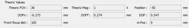
For exemple, the above screenshot shows the results at the current rail position (-50mm) :
- Theoric FOV : If you move your ruler and put it in focus, you should read approximately 36mm.
- Theoric Mag : This FOV corresponds to a x1 Magnification.
- DOFn, DOFn and DOF : Depth of Field calculation. You can check them with a ruler positionned on the Sensor-Lens axis.
- Front Focus dist : The distance between the Focus Plane and the Front Principal Plane.
∞ Pos : The rail position where the focus would be set to infinity. If this position is lower than the Upper Limit then it’s value becomes blue. If this position is lower than the Range End position (or the Range Start then it’s value becomes red.
In this group you can quickly target some particular positions :
- FOV : When you enter a FOV value that you want to reach and hit ENTER, the rail will move to the position giving this FOV.
- Magnification : When you enter a Magnification value that you want to reach and hit ENTER, the rail will move to the position giving this Magnification. If you want to go to infinity, just enter 0.
- Hyperfocal : The rail will move to the nearest position where the DOFf is reaching infinity.
- ∞ : The rail will move to the position where the focus plane is at infinity.
Setting your Start and End point
Now you just need to select a good starting position (Set Start), a good ending position (Set End) and hit the ![]() button.
button.
The sequence will move the rail to the starting position, do it’s first shoot then calculate its next move based on the DOFf and the DOF Overlap ratio (see Preferences Window). It will continue like that until it reaches the End Position (or the Upper Limit) (or the ∞ Pos).
The result should be a nice stack of pictures, giving you an infinite DOF from macro to landscape.
Preferences
Here is the Preferences window :

Sequence Group
Look at your Stackshot documentation. These parameters are the same.
Adaptive Bellows Group
These parameters are dedicated to the Adaptive Bellows Operation Mode.
- Max Circle of Confusion : This textfield allows you to define a specific ratio (relative to pixel size) at which diffraction would become limiting.
- DOF Overlap : This textfield determines the needed Depth of Field overlapping between 2 consecutive pictures. If set to 1, the next position of the focusing plane will be the farthest (or nearest – depending on the direction of the sequence) position of the previous DOF. If set to 0.5, the next position of the focusing plane will be half the farthest (or nearest) of the previous DOF.
Defaults Button
Put back preferences values at their default values.