Mental Blossoming Lamp
Introduction
Macro-Toolbox Mental Blossoming Lamp is a mental controllable lamp.
You can use it to train your attention/concentration and meditation skills.

This lamp is :
- 3d printable with a 3d printer having a printable volume of 130x130x130.
- filled with simple electronics hardware (Arduino board, bluetooth module, led, servo motor). No need to use a phone.
- fully open source (design, hardware and software) and you can adapt it to your needs.
- controllable with a EEG headset (currently a neurosky mindwave mobile headset) with Bluetooth communication.
Design was :
Initiated by emmett and his Blossoming Lamp :
http://www.thingiverse.com/thing:37926
Adapted by Puzzlebox to allow the inclusion of hardware and the motorization :
http://www.thingiverse.com/thing:618490
And finaly the bulb was modded by macro-toolbox to allow its printing with support.
Hardware was :
Initiated by Puzzlebox and,
Modded by macro-toolbox to add the following improvements :
- headset can communicate directly with the lamp.
- no more need of a ble bluetooth board and a ble bluetooth device (phone or tablet) as an interface between the headset and the lamp.
- added a power board to drive the servo and to support the bluetooth module.
Software was :
Based on Neurosky Arduino example found at neurosky.com for the mindwave protocol and,
Fully written by macro-toolbox to control the lamp features (light and motorization), at the exception of a bit of puzzlebox code for the rgb loop crossfade.
Printing
The rendered and OpenScad files can be downloaded from Thingiverse at the following link :
http://www.thingiverse.com/thing:1161390
You should be able to print all stl files without support, except, maybe the bulb.
The bottom, clip and cover components are optional.
The 2 following components can give you some difficulties :
- bloom : you may have to try different speed and.or different filament diameter to succeed.
- bulb : you may need to use support, but the bulb has been reinforced at some points to allow you to remove it securely.
Once your print jobs are done you should have the following :

Hardware
These instructions will use the following parts :
- Arduino Leonardo (x1)
- HC-05 Bluetooth Module (x1)
- Hitec HS-311 Servo Motor (x1)
- RGB Led with common cathode (x1)
- 100Ω Resistor (x1)
- 150Ω Resistors (x2)
- 37×55 Stripboard with 55mm strips (x1)
- 7805 Power Regulator (x1)
- 10µF Capacitor (x2)
- 0.1µF Capacitor (x1)
- Female 3 pins Right Angle 2.54mm Header (x1)
- Female 6 pins Right Angle 2.54mm Header (x2)
- 9V or 12V 1A Power Adapter (x1)
Arduino Board
Why a Leonardo board?
Just because the USB connector is a micro one and, then, we don’t have to make a HUGE hole in our lamp 🙂
Anyway, you’ll be able to use any board that you want or have. Just be careful that the lamp 3d printed parts are physically compatible (or you’ll have to modify them).
Power and Bluetooth board
We’ll start with the creation of this dedicated board.
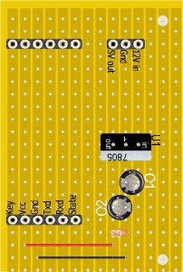 Cut a part of stripboard as on the left image.
Holes have to be drilled at the vertical position of the Arduino board holes (power side).
No strip cut needed.
On the right of the stripboard is the 12V->5V converter.
C1 : 10µF
C2 : 10µF
C3 : 0.1µF
On the left, the 2×6 pins headers are to plug the HC-05 and then to connect the strips to the arduino pins.
A strap is soldered between our regulated 5V and the HC-05 5V pin.
Same for ground.
Warning!
Check that your HC-05 backboard has the same position for 5V, GND, RX and TX. Adapt the schematic if necessary.
Warning!
Your HC-05 backboard could have no 5V pin… In this case don’t solder the 5V wire. You’ll just have to connect a wire between the arduino 3.3V pin and the HC-05 3.3V pin.
Power converter
Let’s check the power we’ll need :
- ~30mA for the arduino.
- 160mA (running current at no load) to 700mA (stall current) for the servo.
- ~30mA (pairing current) for the HC-05.
- 3x20mA for the RGB led.
This gives us a total of 820mA if servo is lifting a load.
It’s generally suggested to let the Arduino board regulator dissipate no more than 1W. It means that with a 12V input, as we have a 7V between the input and output tension, we’ll just be able to have an output current of 140mA (1W/7V=140mA).
As it’s not enough we need to add a power module.
However, as we need less than 1A we can use the Vin pin of Arduino to draw 12V and 1A (if we power Arduino with a 12V adapter in it’s jack power socket).
This will allow us to avoid the soldering of wires on the DC connector.
All that said, let’s go back to our board.
Gnd pin will have to be connected to a Gnd pin on Arduino.
12V pin will have to be connected to the Vin pin on Arduino.
Bluetooth bracket
Our board will also support our HC-05 module.
You can solder the HC-05 directly on the stripboard or use a angled header for that.
I opted for the header solution.
As 5v and ground are directly soldered on the board, and the lamp will just need the TX signal of the HC-05 to operate, only 1 wire will be needed to be routed to Arduino (!).
However, during the configuration process we’ll be happy to have all HC-05 pins easily available. See that later.


HC-05 module
Do you have a HC-05 and will it work ?
There are tons of HC-05 tutorials on the web (this one is great) so I’ll just point what I feel is really important.
HC-05 is a small master/slave bluetooth module and can be bought as is or soldered on a 6 pin backboard.
HC-05 is visually identical to HC-06 whereas the last can only be a slave.
You could change the firmware to convert a HC-05 to a HC-06 (or or the contrary).
HC-05 has a AT mode allowing you to set the master mode (paired devices for example).
HC-06 has no AT mode.
The module itself :

Examples of HC-05 (or maybe HC-06) on their backboard :


Their are hundreds of backboard and features vary from one to one, but what is the most important is that, if your module is a HC-05, whatever the backboard is, you’ll be able to use it.
What you really need is a pin for ground, a pin for power (5V ou 3.3V) and TX/RX. Other pins (EN, STATE, …), leds, button to activate AT mode, etc… are not strictly needed.
Likewise the only solder points really needed between the module and it’s backboard ar pins 1, 2, 12 and 13.
Don’t panic if you see that a lot of points are not soldered.
The only other point which is needed is the 34 (KEY). But if it’s not soldered it’s not a problem.
In short, if you really have a HC-05 module, then you’ll be able to use it in our lamp.
To confirm that you have a HC-05, you can power it :
- connect gnd on pin 13 of the module or on GND pin of it’s pcb and,
- connect 3.3V on pin 12 of the module or on 3.3V of the PCB (if you have a 5V compatible PCB you can also connect 5V to the good pin).
Then check with a bluetooth computer or phone if you can see a device named HC05.
Notice!
If your phone is not pre-Bluetooth 4 (ble) compatible, it could see anything.
If you see a HC05 device in your bluetooth list, then you have the good one.

Toggle to AT Mode
Before being able to use the module in our lamp, we have to toggle it in AT mode. This mode will allow you to configure the module as a master device.
Let’s begin with some theory.
The secure way to have the HC-05 communicate with an Arduino board is as following :

Based on the powering option of your HC-05 backboard you’ll use de 5V or 3.3V Arduino’s outputs to power the module.
Before going further, I have to clarify a point.
Even if your HC-05 module is 5V compatible, its TX/RX lines have a 3.3V level.
It means that the TX of HC-05 will output a 3.3V TTL signal and its RX expect a 3.3V input signal.
The HC-05’s 3.3V TX is not a problem as Arduino’ RX will trigger at this level.
On the contrary the 3.3V expected at the RX of HC-05 could be a problem as Arduino’s TX is 5V.
This explains the presence of the 2 resistors which act as a divider and lower the TX 5V signal to a 3.3V one.
Even so, As we just have to send a few commands only once (at initial configuration), it is possible to take the risk and directly connect Arduino’s TX on the HC-05’s RX.
Please don’t blame me if your HC-05 fries… Or use the divider.
Enough for explanations. Now, the concrete things.
1. Upload the following sketch in your arduino :
#include <SoftwareSerial.h>
SoftwareSerial BTSerial(2, 3); // RX | TX
void setup() {
    Serial.begin(9600);
    Serial.println("Enter AT commands:");
    BTSerial.begin(38400);  // HC-05 default speed in AT command more
}
void loop() {
    // Keep reading from HC-05 and send to Arduino Serial Monitor
    if (BTSerial.available())
      Serial.write(BTSerial.read());
    // Keep reading from Arduino Serial Monitor and send to HC-05
    if (Serial.available())
      BTSerial.write(Serial.read());
}
As you can see, we’ll use the Arduino as a simple serial interface between its serial console and the HC-05.
As the console needs ports 0 and 1 of the Arduino to be free we use the ports 2 and 3 for serial communication with HC-05 (with help of SoftwareSerial).
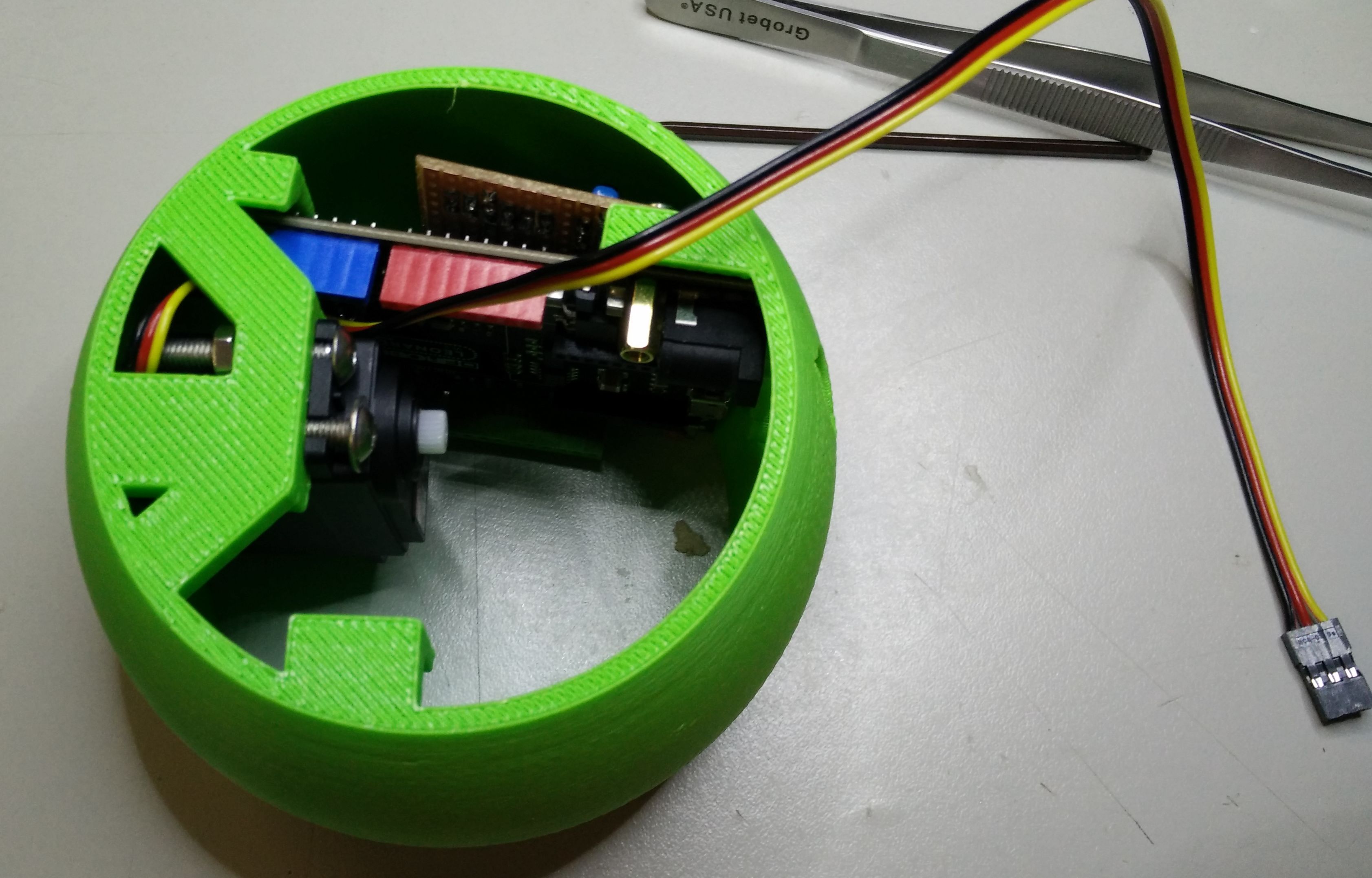
2. Now let’s do the following assembly :

3. let’s enter AT mode :
First we will start at this point :

As you can see Arduino is not powered.
Second, we take the flying jumper wire (3.3V) and make it touch pin 34 of HC-05 module (the upper right point). We maintain this contact.

Third, push the usb plug into the Arduino to power Arduino and HC-05 (while maintaining contact on pin 34).
Fourth, we wait a few seconds until the HC-05 led start blinking slowly (2s on, 2s off).
Fifth, we are in AT mode.
Notice!
If, at this point, HC-05 doesn’t blink slowly, you failed and you just have to unplug Arduino and retry.
Let’s open Arduino’s console to communicate with HC-05.
Configure the console at [js]9600 baud[/js] and check that [js]Both NL & CR[/js] is selected instead of [js]no line ending[/js].
If all is OK you should see the line [js]Enter AT commands:[/js] appearing at the top of the console.

Configure HC-05 as Master
You will need just one information to do the HC-05 Master configuration : Your Headset MAC address.
To find it you will need to power this headset and set in in pairing mode (you push upward the power button during about 5s until the blue led blink two times). Refer to your headset documentation if needed.
Once your headset is in pairing mode you will need to use a computer or a phone to detect your headset bluetooth device and find its MAC address. Your headset will be named ‘Mindwave Mobile’.
A MAC address looks like 20:68:9D:79:D5:51 and you can use applications to show it. Under android, I can suggest ‘Bluetooth spp tools pro’.
Once you have your headset MAC address you can go on and return to your Arduino console.
Now you can type the following commands in the console (one line at a time) .
In this command list you have to adjust AT+NAME and AT+BIND to your needs :
AT+NAME : just choose the name you want for your lamp.
AT+BIND : get your headset MAC address and reformat it as needed. Eg : If your MAC address is 20:68:9D:79:D5:51, you’ll have to send it as 2068,9D,79D551.
AT+NAME=LAMP
AT+UART=57600,0,0
AT+ROLE=1
AT+PSWD=0000
AT+CMODE=0
AT+BIND=2068,9D,79D551
AT+IAC=9E8B33
AT+CLASS=0
AT+INQM=1,9,48
HC-05 should answer [js]OK[/js] each time.
You can check if your parameters are correctly saved in HC by retyping each command without its parameter and with a ? character at the end. Example : [js]AT+UART?[/js].
Here is the full log after configuration of HC-05 :

Notice!
It seems that some commands like AT+NAME? and AT+CLASS? don’t send back their parameter . Don’t worry about it.
You can now disconnect Arduino and unplug the HC-05 module. We have finished with it 🙂
Now to test if it works, re-plug the board, switch on your headset and set it to pairing mode. It will start to blink 2 times and you should see that the blinking on the HC-05 becomes slower : the devices are paired.
RGB LED
How to choose the good resistors?
Look at the datasheet of your LED and you will find a parameter named Forward Voltage.
 There you will understand that each leg has a different value for this parameter :
- Red : 2.0V
- Green : 3.2V
- Blue 3.2V
As we’ll power led with Arduino’s output at 5V max and that each output can only deliver 20mA, we can calculate the resistor for each leg:
- Red : (5-2.0)/20=150Ω -> we’ll keep it to 150Ω
- Green : (5-3.2)/20=91Ω-> we’ll round it to 100Ω
- Blue : (5-3.2)/20=91Ω-> we’ll round it to 100Ω
Notice!
If you want some security, use 1×150Ω and 2×220Ω.
We will now solder those resistors at each legs of the LED.
How to know which pins are what?
Look at the datasheet and you’ll get what you need :

Now solder those resistors on the good pins, like that :

Before doing the last solder points, don’t forget to engage some heat shrink on each wire.
Shift the position of each resistor to avoid obstruction when you’ll slide this in the bulb.
Here is the finished device :

Software
If you are in a hurry you can unhide and copy the Full Code bellow, upload it to your Arduino and jump to the next chapter.
https://github.com/mtbox0/mental_blossoming_lamp
/**
 * macro-toolbox Mental Blossoming Lamp
 * Copyright (c) 2010-2015, macro-toolbox.com and others.
 *
 * All rights reserved. This program and the accompanying materials
 * are made available under the terms of the GNU Pulic License (GPL) version 3
 * which accompanies this distribution, and is available at
 * http://www.gnu.org/licenses/gpl-3.0.en.html
 *
 * Some parts of this code was written by neurosky or puzzlebox. These parts
 * have been marked like so.
 */

//Configure HC-05 as follow
//AT+NAME=BLOOM
//AT+UART=57600,0,0
//AT+ROLE=1
//AT+PSWD=0000
//AT+CMODE=0
//AT+BIND=2068,9D,79D551 (Mindwave Unique Number)
//AT+IAC=9E8B33
//AT+CLASS=0
//AT+INQM=1,9,48

//number of plots in our remap curves
//Nota : must be defined before any code as it's used in function definition
#define NBPLOTS 10

#include <Servo.h>
Servo myservo ; // Create the Servo object

//pins definition
#define RED_PIN 3
#define GREEN_PIN 5
#define BLUE_PIN 6
#define LEDGND_PIN 7
#define SERVO_PIN 2

#define TERMBAUDRATE 57600
#define BTBAUDRATE 57600

//uncomment to allow usb serail monitoring
//Leonardo use Serial1 for TTL and Serial for USB
#define MONITORING
#ifdef MONITORING
//if you want to use other Serial port then adapt line bellow
#define BT_BEGIN(x)			Serial1.begin(x);while (!Serial1) {}
#define BT_AVAILABLE		Serial1.available
#define BT_READ				Serial1.read
#define TERM_BEGIN(x)		Serial.begin(x)
#define TERM_PRINT(x)		Serial.print (x)
#define TERM_PRINTLN(x)		Serial.println (x)
#define TERM_PRINTDEC(x)	Serial.print (x, DEC)
#define TERM_PRINTDECLN(x)	Serial.println (x, DEC)
//uncomment if you want to log every byte received from BT
//Nota : if you uncomment, you have to adapt TERMBAUDRATE to be at
//least equal to BTBAUDRATE
//#define DEBUGOUTPUT
#else
#define BT_BEGIN(x)			Serial1.begin(x);while (!Serial1) {}
#define BT_AVAILABLE		Serial1.available
#define BT_READ				Serial1.read
#define TERM_BEGIN(x)
#define TERM_PRINT(x)
#define TERM_PRINTLN(x)
#define TERM_PRINTDEC(x)
#define TERM_PRINTDECLN(x)
#endif


byte attention = 0;
byte meditation = 0;
unsigned int rgbColour[3];
const int servoOpenedAngle = 10;
const int servoClosedAngle = 90;

void setup(){
    TERM_BEGIN(TERMBAUDRATE);			// USB
    BT_BEGIN(BTBAUDRATE);
    pinMode(RED_PIN, OUTPUT);
    pinMode(GREEN_PIN, OUTPUT);
    pinMode(BLUE_PIN, OUTPUT);
        pinMode(LEDGND_PIN, OUTPUT);
        digitalWrite(LEDGND_PIN, LOW);
    // Start off with red.
    rgbColour[0] = 255;
    rgbColour[1] = 0;
    rgbColour[2] = 0;

    myservo.attach(SERVO_PIN);
    myservo.write(servoClosedAngle);//servoClosedAngle);
}

void remapAndRamp(float input, float &target, float &result, float increment, float decrement, const float plots[NBPLOTS][2]){
    if(target>result) {
        result+=increment;
        if(result>target) result=target;
    }
    else if(target<result) {
        result-=decrement;
        if(result<target) result=target;
    }

    for(int i=0;i<NBPLOTS;i++) {
        if(input<=plots[i][0]) {
            target=plots[i][1];
            break;
        }
    }
}

//eeg manager
float eegResult = 0;
//change below if you want a slower/faster reactivity of EEG
//lower : slower response
//highr : faster response
const float difficultyCoef=0.5;
void eegManager(){
    static float attentionTarget = 0;
    static float attentionResult = 0;
    static float meditationTarget = 0;
    static float meditationResult = 0;
    static unsigned long lastEegManagerMillis=0;

    if((millis()-lastEegManagerMillis) > 10) {
        lastEegManagerMillis=millis();

        //eeg result transformation curve
        const float eegPlots [NBPLOTS][2] = {
            {10,0.0}, {20,2.0}, {30,5.0}, {40,15.0}, {50,30.0},
            {60,50.0}, {70,75.0}, {80,95.0}, {90,100.0}, {100,100.0}};
        //process eeg headset values
        remapAndRamp(attention, attentionTarget, attentionResult, .1*difficultyCoef, .05*difficultyCoef, eegPlots);
        remapAndRamp(meditation, meditationTarget, meditationResult, .1*difficultyCoef, .05*difficultyCoef, eegPlots);
        eegResult=max(attentionResult, meditationResult);
    }
}

//candle manager
float candlePowerResult=0;
void candleManager(){
    static float candlePowerTarget=0;
    static unsigned long candleDelay=0;
    static unsigned long lastCandleManagerMillis=0;

    if((millis()-lastCandleManagerMillis) > candleDelay) {
        lastCandleManagerMillis = millis();
        candleDelay = random(50)+10;

        //candle power curve
        const float candlePlots [NBPLOTS][2] = {
            {10,0.0}, {20,1.0/100}, {30,2.0/100}, {40,4.0/100}, {50,7.0/100},
            {60,10.0/100}, {70,6.0/100}, {80,2.0/100}, {90,1.0/100}, {100,0.0}};
        //process candle power
        remapAndRamp(eegResult, candlePowerTarget, candlePowerResult, .01, .02, candlePlots);
        //candle blink
        candlePowerTarget = candlePowerTarget*((float)random(3)+1);
    }
}

//rgbLoop manager
float rgbLoopPowerResult=0;
void rgbLoopManager() {
    static float rgbLoopPowerTarget=0;
    static int decColour = 0;
    static int colorIncrement=0;
    static unsigned long lastRgbLoopMillis=0;

    if((millis()-lastRgbLoopMillis) > 20) {
        lastRgbLoopMillis = millis();

        //start of puzzlebox code
        //please refer to https://github.com/PuzzleboxIO/bloom-design/tree/master/firmware/Bloom for the original
        // Choose the colours to increment and decrement.
        int incColour = decColour == 2 ? 0 : decColour + 1;
        // cross-fade the two colours.
        rgbColour[decColour] -= 1;
        rgbColour[incColour] += 1;
        colorIncrement+=1;
        if(colorIncrement==255) {
            colorIncrement=0;
            decColour+=1;
            if(decColour==3) decColour=0;
        }
        //end of puzzlebox code

        //rgbLoop power curve
        const float rgbLoopPlots [NBPLOTS][2] = {
            {10,0.0}, {20,0.0}, {30,0.0}, {40,0.0}, {50,0.0},
            {60,5.0/100}, {70,10.0/100}, {80,50.0/100}, {90,95.0/100}, {100,1.0}};
        //process rgbLoop power
        remapAndRamp(eegResult, rgbLoopPowerTarget, rgbLoopPowerResult, .001, .001, rgbLoopPlots);
    }
}

//light manager
void lightManager(){
    candleManager();
    rgbLoopManager();
    float rval = rgbLoopPowerResult*rgbColour[0];
    rval += candlePowerResult*0xFF; //orange
    if(rval>255) rval=255;
    float gval = rgbLoopPowerResult*rgbColour[1];
    gval += candlePowerResult*0x99; //orange
    if(gval>255) gval=255;
    float bval = rgbLoopPowerResult*rgbColour[2];
    bval += 0; //orange

    analogWrite(RED_PIN, (int)rval);
    analogWrite(GREEN_PIN, (int)gval);
    analogWrite(BLUE_PIN, (int)bval);
}

//servo amplitude manager
float servoAmplitudeResult=0;
void servoAmplitudeManager(){
    static float servoAmplitudeTarget=0;
    static unsigned long lastServoAmplitudeManagerMillis=0;

    if((millis()-lastServoAmplitudeManagerMillis) > 100) {
        lastServoAmplitudeManagerMillis = millis();

        //amplitude curve
        const float servoAmplitudePlots [NBPLOTS][2] = {
            {10,0.0}, {20,0.0}, {30,10.0}, {40,20.0}, {50,32.0},
            {60,45.0}, {70,62.0}, {80,80.0}, {90,90.0}, {100,100.0}};
        //process servo amplitude
        remapAndRamp(eegResult, servoAmplitudeTarget, servoAmplitudeResult, .5, .5, servoAmplitudePlots);
    }
}

//motor manager
const int servoPauseTime = 3000;
void servoManager(){
    static float servoAngleTarget=0;
    static float servoAngleResult=0;
    const int OPENING=0;
    const int CLOSING=1;
    const int WILLOPEN=2;
    const int WILLCLOSE=3;
    static int servoState = OPENING;
    static unsigned long lastServoManagerMillis=0;
    static unsigned long lastServoStateChangeMillis=0;

    servoAmplitudeManager();

    if((millis()-lastServoStateChangeMillis) > servoPauseTime) {
        lastServoStateChangeMillis = millis();
        if(servoState==WILLOPEN) servoState=OPENING;
        if(servoState==WILLCLOSE) servoState=CLOSING;
    }

    if((millis()-lastServoManagerMillis) > 50){
        lastServoManagerMillis = millis();
        //angle opening curve
        const float servoOpeningAnglePlots [NBPLOTS][2] = {
            {10,0.0}, {20,20.0}, {30,30.0}, {40,40.0}, {50,50.0},
            {60,60.0}, {70,70.0}, {80,80.0}, {90,90.0}, {100,100.0}};
        const float servoClosingAnglePlots [NBPLOTS][2] = {
            {10,0.0}, {20,0.0}, {30,0.0}, {40,0.0}, {50,0.0},
            {60,0.0}, {70,0.0}, {80,0.0}, {90,0.0}, {100,0.0}};
        //process servo angle
        if(servoState==OPENING) {
            remapAndRamp(servoAmplitudeResult, servoAngleTarget, servoAngleResult, 1, 0.8, servoOpeningAnglePlots);
            if(servoAngleResult>=servoAngleTarget) servoState=WILLCLOSE;
        }

        if(servoState==CLOSING){
            remapAndRamp(servoAmplitudeResult, servoAngleTarget, servoAngleResult, 1, 1.2, servoClosingAnglePlots);
            if(servoAngleResult<=servoAngleTarget) servoState=WILLOPEN;
        }

        int angle = map(servoAngleResult, 0, 100, servoClosedAngle, servoOpenedAngle);
        //TERM_PRINT(" angle: ");
        //TERM_PRINTDECLN(angle);
        myservo.write(angle);
    }
}


//start of neurosky code
//please refer to http://developer.neurosky.com/docs/doku.php?id=arduino_tutorial for the original
////////////////////////////////
// Read data from Serial UART //
////////////////////////////////
unsigned long lastReceivedPacketMillis = 0;
byte ReadOneByte(){
    int ByteRead;
    while(!BT_AVAILABLE()){
        eegManager();
        lightManager();
        servoManager();

    };

    ByteRead = BT_READ();
#ifdef DEBUGOUTPUT
    TERM_PRINT((char)ByteRead);	  // echo the same byte out the USB serial (for debug purposes)
#endif
    lastReceivedPacketMillis = millis();
    return ByteRead;
}
/////////////
//MAIN LOOP//
/////////////
void loop(){
    static byte generatedChecksum = 0;
    static byte checksum = 0;
    static int payloadLength = 0;
    static byte payloadData[64] = {0};
    static byte poorQuality = 200;

    static boolean bigPacket = false;


    // Look for sync bytes
  	if(ReadOneByte() == 170){
        if(ReadOneByte() == 170){
            //TERM_PRINTLN("nada");
            payloadLength = ReadOneByte();
            if(payloadLength > 169)			 //Payload length can not be greater than 169
                return;
            generatedChecksum = 0;
            for(int i = 0; i < payloadLength; i++){
                payloadData[i] = ReadOneByte();			   //Read payload into memory
                generatedChecksum += payloadData[i];
            }
            checksum = ReadOneByte();		  //Read checksum byte from stream
            generatedChecksum = 255 - generatedChecksum;   //Take one's compliment of generated checksum
            if(checksum == generatedChecksum){
                for(int i = 0; i < payloadLength; i++) {
                    // Parse the payload
                    switch (payloadData[i]){
                        case 2:
                            i++;
                            poorQuality = payloadData[i];
                            bigPacket = true;
                            break;
                        case 4:
                            i++;
                            attention = payloadData[i];
                            break;
                        case 5:
                            i++;
                            meditation = payloadData[i];
                            break;
                        case 0x80:
                            i = i + 3;
                            break;
                        case 0x83:
                            i = i + 25;
                            break;
                        default:
                            break;
                    } // switch
                } // for loop
#ifndef DEBUGOUTPUT
                //*** Add your code here ***
                if(poorQuality!=0) digitalWrite(13, HIGH);
                else digitalWrite(13, LOW);
                if(bigPacket){
                    TERM_PRINT("PoorQuality: ");
                    TERM_PRINTDEC(poorQuality);
                    TERM_PRINT(" Attention: ");
                    TERM_PRINTDEC(attention);
                    TERM_PRINT(" Meditation: ");
                    TERM_PRINTDEC(meditation);
                    TERM_PRINT(" eegResult: ");
                    TERM_PRINTDECLN(eegResult);
                }
#endif
                bigPacket = false;
            } else {
                // Checksum Error
            }	 // end if else for checksum
        } // end if read 0xAA byte
    } // end if read 0xAA byte
}
//end of neurosky code
If you have time, unhide this and I’ll give you some explanation of what is done in this sketch.
eegResult calculation
eegResult is a calculated variable used by the lamp to know what state it has to show (through light and motor actions).
As, the EEG headset transmits its measurements every second and these values are a bit raw, we need this intermediate eegResult variable :
First, if we consider that full attention(for example) is equals to a headset value of 100, then our user will be very frustrated as he rarely reach this value.
Second, you can have a huge amplitude between one measure and the next one : if we use these values as is, our lamp will behave erratically (full light during one second, no light the next second, etc…).
Therefore, we will do some processing to headset values in two forms :
- curve transformation to respond to the first problem
- temporal transformation to respond to the second one
Headset Eeg values curve transformation
First, we remap the EEG input values (from headset) to new values to take in account that if the headset value is bellow 30 then it’s almost null (attention/meditation) and, that if the headset value is above 80 then it’s almost full(attention/meditation).
We use this curve :
http://fooplot.com/plot/soj8552685

We do this on the headset values (attention and meditation) every 10ms (even if updates are send by the headset only every seconds – it’s not a problem).
This gives us 2 calculated targets : attentionTarget and meditation Target.
Here what it could gives for the calculation of attentionTarget :
//every 10ms
if(attention<=10) attentionTarget=0;
else if(attention<=20) attentionTarget=2;
else if(attention<=30) attentionTarget=5;
else if(attention<=40) attentionTarget=15;
else if(attention<=50) attentionTarget=30;
else if(attention<=60) attentionTarget=50;
else if(attention<=70) attentionTarget=75;
else if(attention<=80) attentionTarget=95;
else if(attention<=90) attentionTarget=100;
else attentionTarget=100;
eegResult temporal processing
Now, as we have a human, non-frustrating, value for his performance, we have to smooth variations in time to have a nice lamp response. The result of this smoothing will be stored in 2 variables : attentionResult and meditation result.
This smoothing is done in the same loop as the above curve transformation (every 10ms) by adding a small positive or negative value to the last value of these result variables.
Always to not frustrate our user, the ramp up is faster than the ramp down :
- ramp up : value increase by 0.1 every 10ms
- ramp down : value decrease by 0.05 every 10ms
To gives you an idea of the result, if user jump from 0 to 100 and stay to 100, the lamp will need 1000 loop to show the full state (namely 10s). I jumping from 100 to 0, it will need 20s.
Now that we have smoothed in time our attention and meditation results, we just set our eegResult variable to the max one of this two results.
eegResult will, now, be the only eeg information to calculate its state and react as needed.
So we could add the following at the bottom of our previous code :
if(attentionTarget>attentionResult) attentionResult+=.1;
else if(attentionTarget<attentionResult) attentionResult-=.05;
if(attentionResult>100)attentionResult=100.0;
if(attentionResult<0)attentionResult=0.0;
eegResult=max(attentionResult);//, meditationResult);
putting this in a function
As We use the same calculation for attention and meditation, and because we’ll, soon, process other values the same way, we will create a function to do all that :
//number of plots in our transormation curves
//Nota : must be defined before any code as it's used in function definition
#define NBPLOTS 10
void remapAndRamp(float input, float &target, float &result, float increment, float decrement, const float plots[NBPLOTS][2]){
    if(target>result) {
        result+=increment;
        if(result>target) result=target;
    }
    else if(target<result) {
        result-=decrement;
        if(result<target) result=target;
    }

    for(int i=0;i<NBPLOTS;i++) {
        if(input<=plots[i][0]) {
            target=plots[i][1];
            break;
        }
    }
}
With this function the eegResult calculation can be done simply like that :
byte attention = 0;
byte meditation = 0;

//eeg manager

float eegResult = 0;
//change below if you want a slower/faster reactivity of EEG
//lower : slower response
//highr : faster response
const float difficultyCoef=0.5;
void eegManager(){
    static float attentionTarget = 0;
    static float attentionResult = 0;
    static float meditationTarget = 0;
    static float meditationResult = 0;
    static unsigned long lastEegManagerMillis=0;

    if((millis()-lastEegManagerMillis) > 10) {
        lastEegManagerMillis=millis();

        //eeg result transformation curve
        const float eegPlots [NBPLOTS][2] = {
            {10,0.0}, {20,2.0}, {30,5.0}, {40,15.0}, {50,30.0},
            {60,50.0}, {70,75.0}, {80,95.0}, {90,100.0}, {100,100.0}};
        //process eeg headset values
        remapAndRamp(attention, attentionTarget, attentionResult, .1*difficultyCoef, .05*difficultyCoef, eegPlots);
        remapAndRamp(meditation, meditationTarget, meditationResult, .1*difficultyCoef, .05*difficultyCoef, eegPlots);
        eegResult=max(attentionResult, meditationResult);
  }
}
You can note that :
- We hard-coded the number of plots in our transformation curves (NBPLOTS) to simplify the transmission of this array.
- We added a difficultyCoef (hard-coded) to adapt the response to the user skill. It would be possible to add a button or potentiometer to let the user change this value… but it’s not in the scope of this project.
Light management
For a nice touch, I decided to mix two effects and to cross-fade them in relation with the EEG level.
I wanted that :
- if EEG level is low, light power must be near 0.
- if EEG level is between a low and a good EEG level, a candle simulation is used. the power of the light increase as EEG level.
- if EEG level is between a good level and max level, the candle simulation will be replaced by the other effect. So, as EEG level increase, the power of candle light must go down to 0.
- simultaneously to the above point, the second effect appears. This one is a color loop and it’s power goes higher as the EEG level climbs.
Let’s look at each managements methods.
Candle Manager
As described, we want a candle power peak when EEG reach a “good” level then we want it to decrease.
So we’ll use this power curve :
http://fooplot.com/plot/afqa65vw86

As you can see the power will only only reach a maximum of 10. Why?
Our candle will be characterized by a orange color. So we’ll have a base RGB value of {255, 153, 0}.
What we need is to apply to this value a power factor. Our curve is this power factor and you can better understand it as a percentage that we’ll apply to our orange color.
It means that at a 60 EEG value we’ll have 10% of the power for a full orange.
Why 60? Because we’ve just decided that it will be the zone where our candle will start to be replaced by our rgb loop.
But why just 10%? It’s weak no?
Yes it’s weak but we’ll multiply this result by a random factor between 1 and 4. This factor will give us a blinking impression.
So our peak value will be 40%. As the Rgb Loop will have already started its ramp up at the same level (see next chapter), we should have a light power peak of, maybe 50. It should be coherent with our EEG level. (don’t worry, I’ve tested it 😉 )
Ok let’s look at the the code.
float candlePowerResult=0;
void candleManager(){
    static float candlePowerTarget=0;
    static unsigned long candleDelay=0;
    static unsigned long lastCandleManagerMillis=0;

    if((millis()-lastCandleManagerMillis) > candleDelay) {
        lastCandleManagerMillis = millis();
        candleDelay = random(50)+10;

        //candle power curve
        const float candlePlots [NBPLOTS][2] = {
            {10,0.0}, {20,1.0/100}, {30,2.0/100}, {40,4.0/100}, {50,7.0/100},
            {60,10.0/100}, {70,6.0/100}, {80,2.0/100}, {90,1.0/100}, {100,0.0}};
        //process candle power
        remapAndRamp(eegResult, candlePowerTarget, candlePowerResult, .01, .02, candlePlots);
        //candle blink
        candlePowerTarget = candlePowerTarget*((float)random(3)+1);
  }
}
As you can see we use our remapAndRamp function to do our target and temporal calculation.
In the plot array, we reported our curve values as percentage.
What is new are :
- The loop has not a constant triggering delay. We use a random delay between 10 and 60ms to try to give a natural candle look to our lamp.
- As said before, we multiply the candlePowerTarget by a random factor between 1 and 4. Also to give natural look to our candle.
It’s not perfect but I like it well 🙂
The variable candlePowerResult is what we’ll soon use to power our led.
Rgb Loop Manager
For the Rgb Loop we’ll just re-use the puzzlebox cross-fade and adapt it to our concept of cross-fading.
First the curve :
http://fooplot.com/plot/ngyygwx661

As expected our power start to climb near a EEG level of 60. The slope is important to reach a near top value à 90. It’s necessary to compensate the vanishing of the candle effect.
As steps are really high we’ll need to use a lower increment/decrement than before to avoid visual flickering.
The code :
unsigned int rgbColour[3];
void setup(){
    // Start off with red.
    rgbColour[0] = 255;
    rgbColour[1] = 0;
    rgbColour[2] = 0;
}

float rgbLoopPowerResult=0;
void rgbLoopManager() {
    static float rgbLoopPowerTarget=0;
    static int decColour = 0;
    static int colorIncrement=0;
    static unsigned long lastRgbLoopMillis=0;

    if((millis()-lastRgbLoopMillis) > 20) {
        lastRgbLoopMillis = millis();
        // Choose the colours to increment and decrement.
        int incColour = decColour == 2 ? 0 : decColour + 1;
        // cross-fade the two colours.
        rgbColour[decColour] -= 1;
        rgbColour[incColour] += 1;
        colorIncrement+=1;
        if(colorIncrement==255) {
            colorIncrement=0;
            decColour+=1;
            if(decColour==3) decColour=0;
        }

        //rgbLoop power curve
        const float rgbLoopPlots [NBPLOTS][2] = {
            {10,0.0}, {20,0.0}, {30,0.0}, {40,0.0}, {50,0.0},
            {60,5.0/100}, {70,10.0/100}, {80,50.0/100}, {90,95.0/100}, {100,1.0}};
        //process rgbLoop power
        remapAndRamp(eegResult, rgbLoopPowerTarget, rgbLoopPowerResult, .001, .001, rgbLoopPlots);
    }
}
Our loop is triggered every 20ms.
The first part of the code is the rgb cross-fade.
The rest is now classical.
Final Light Manager
This is trivial and here is the code :
//pins definition
#define RED_PIN 3
#define GREEN_PIN 5
#define BLUE_PIN 6
#define LEDGND_PIN 7

void setup(){
    pinMode(RED_PIN, OUTPUT);
    pinMode(GREEN_PIN, OUTPUT);
    pinMode(BLUE_PIN, OUTPUT);
    pinMode(LEDGND_PIN, OUTPUT);
    digitalWrite(LEDGND_PIN, LOW);
    /*
    ...
    */
}

void lightManager(){
    candleManager();
    rgbLoopManager();
    float rval = rgbLoopPowerResult*rgbColour[0];
    rval += candlePowerResult*0xFF; //orange
    if(rval>255) rval=255;
    float gval = rgbLoopPowerResult*rgbColour[1];
    gval += candlePowerResult*0x99; //orange
    if(gval>255) gval=255;
    float bval = rgbLoopPowerResult*rgbColour[2];
    bval += 0; //orange

    analogWrite(RED_PIN, (int)rval);
    analogWrite(GREEN_PIN, (int)gval);
    analogWrite(BLUE_PIN, (int)bval);
}
Servo management
Amplitude Manager
As always we want to remap and ramp the EEG level to another one 🙂
This time want we want to achieve is the calculation of an amplitude percentage dependent of the EEG level.
With this amplitude value, we’ll be able to open, more or less, the petals.
When EEG level will be at the top, the flower will open fully and, with lower levels, it will open less.
Easy, here is the curve :
http://fooplot.com/plot/fm39gz01u9

And the code :
//servo amplitude manager
float servoAmplitudeResult=0;
void servoAmplitudeManager(){
    static float servoAmplitudeTarget=0;
    static unsigned long lastServoAmplitudeManagerMillis=0;

    if((millis()-lastServoAmplitudeManagerMillis) > 100) {
        lastServoAmplitudeManagerMillis = millis();

        //amplitude curve
        const float servoAmplitudePlots [NBPLOTS][2] = {
            {10,0.0}, {20,0.0}, {30,10.0}, {40,20.0}, {50,32.0},
            {60,45.0}, {70,62.0}, {80,80.0}, {90,90.0}, {100,100.0}};
        //process servo amplitude
        remapAndRamp(eegResult, servoAmplitudeTarget, servoAmplitudeResult, .5, .5, servoAmplitudePlots);
    }
}
This time we trigger every 100ms as there is no need to have fast response. And consequently we use higher increment/decrement.
Servo Manager
Now that we have a dynamic amplitude value that we can use when we want, we only have to make the servo open or close the lamp.
As I really like our remapAndRamp function, we’ll still use it 🙂
We’ll start our lamp in an OPENING state and we will make it opens until the current value of amplitude, then we’ll make it sleep some seconds and the lamp will pass in a CLOSE status etc..
Here is the code :
//motor manager
const int servoPauseTime = 3000;
void servoManager(){
    static float servoAngleTarget=0;
    static float servoAngleResult=0;
    const int OPENING=0;
    const int CLOSING=1;
    const int WILLOPEN=2;
    const int WILLCLOSE=3;
    static int servoState = OPENING;
    static unsigned long lastServoManagerMillis=0;
    static unsigned long lastServoStateChangeMillis=0;

    servoAmplitudeManager();

    if((millis()-lastServoStateChangeMillis) > servoPauseTime) {
        lastServoStateChangeMillis = millis();
        if(servoState==WILLOPEN) servoState=OPENING;
        if(servoState==WILLCLOSE) servoState=CLOSING;
    }

    if((millis()-lastServoManagerMillis) > 50){
        lastServoManagerMillis = millis();
        //angle opening curve
        const float servoOpeningAnglePlots [NBPLOTS][2] = {
            {10,0.0}, {20,20.0}, {30,30.0}, {40,40.0}, {50,50.0},
            {60,60.0}, {70,70.0}, {80,80.0}, {90,90.0}, {100,100.0}};
        const float servoClosingAnglePlots [NBPLOTS][2] = {
            {10,0.0}, {20,0.0}, {30,0.0}, {40,0.0}, {50,0.0},
            {60,0.0}, {70,0.0}, {80,0.0}, {90,0.0}, {100,0.0}};
        //process servo angle
        if(servoState==OPENING) {
            remapAndRamp(servoAmplitudeResult, servoAngleTarget, servoAngleResult, 1, 0.8, servoOpeningAnglePlots);
            if(servoAngleResult>=servoAngleTarget) servoState=WILLCLOSE;
        }

        if(servoState==CLOSING){
            remapAndRamp(servoAmplitudeResult, servoAngleTarget, servoAngleResult, 1, 1.2, servoClosingAnglePlots);
            if(servoAngleResult<=servoAngleTarget) servoState=WILLOPEN;
        }

        int angle = map(servoAngleResult, 0, 100, servoClosedAngle, servoOpenedAngle);
        //TERM_PRINT(" angle: ");
        //TERM_PRINTDECLN(angle);
        myservo.write(angle);
    }
}
The two curves are a bit surprising but, when opening, I really just need the ramp functionality of remapAndRamp. So the curve is just a 1 to 1 conversion (except for the first plot as I needed to start with a zero angle value.
When closing, it even more subtle 🙂 We just always want a zero angle target.
I won’t analyse the remains of the code (main loop) as this one is nearly pure neurosky code and I just inserted somewhere in this loop a call to our 3 main functions (eegManager, lightManager and servoManager).
Once done, everything should run fine.
Assembly
We can finally put all this together 🙂
Here are the main actors on the stage. for a have a better show, I printed a incomplete base.
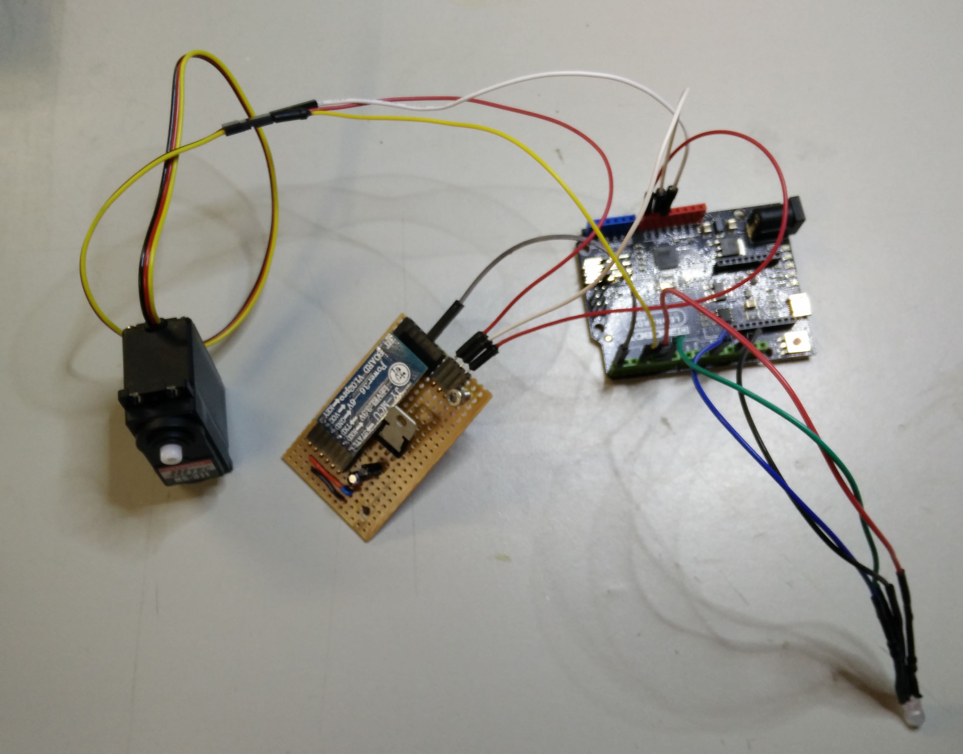
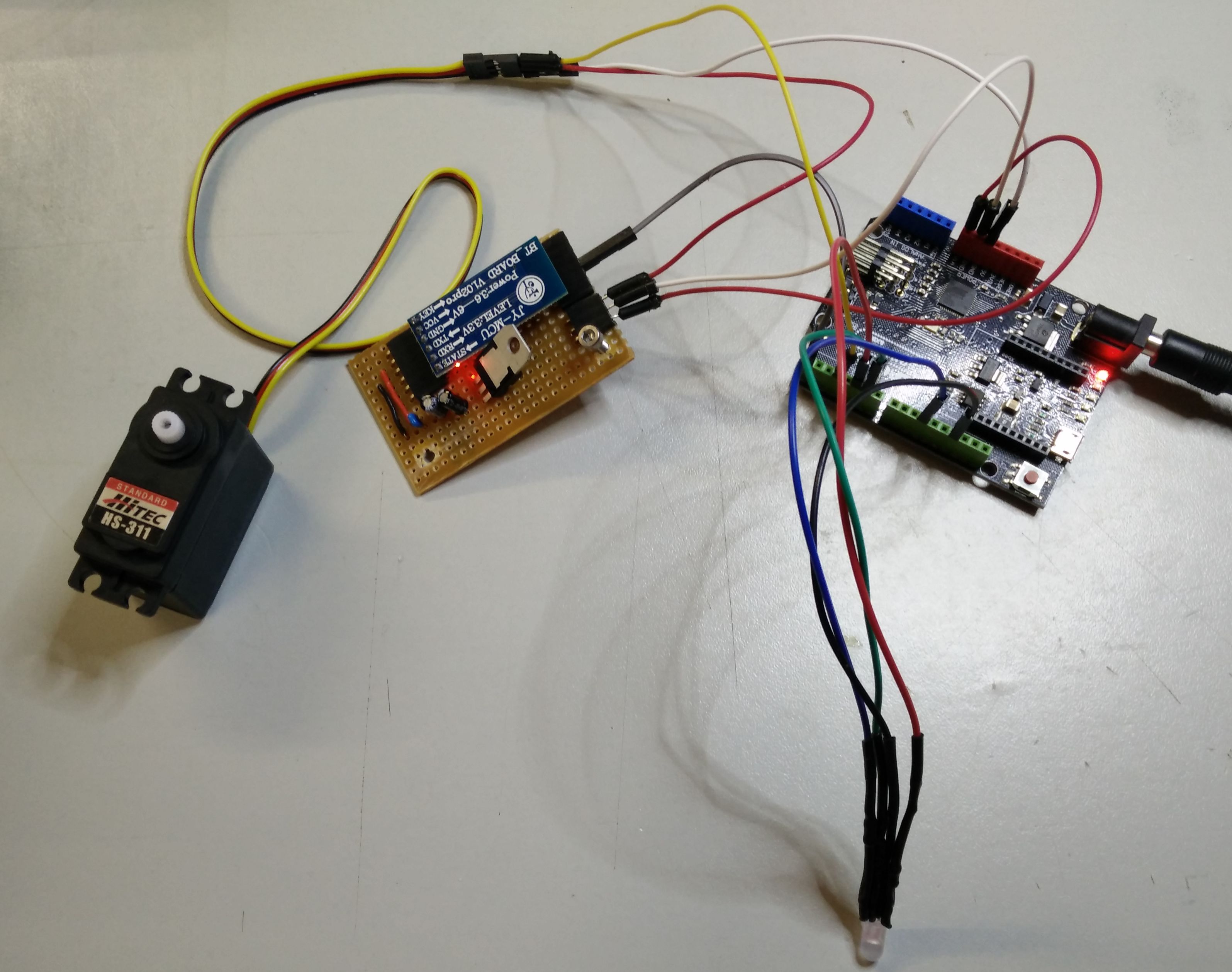
 The mounting scheme to wire them all :

Notice!
Don’t care about the the pins used on the next 2 photos, there are not the final ones (I pictured them before assigning final pins). Use scheme above as a target for your assembly.

First of all, you’ll have to test your program and components. Wire everything as on above, power the Arduino board and switch on your EEG headset. As you manage to level your EEG level (attention or meditation) the led will start to light and the motor will begin to spin.

Once all reacts, unplug the power jack, switch off your headset and plug back the power jack. This will set the servo motor to its zero position.
When done, unplug the power jack and try to avoid turning the motor axe until the connection of its arm.

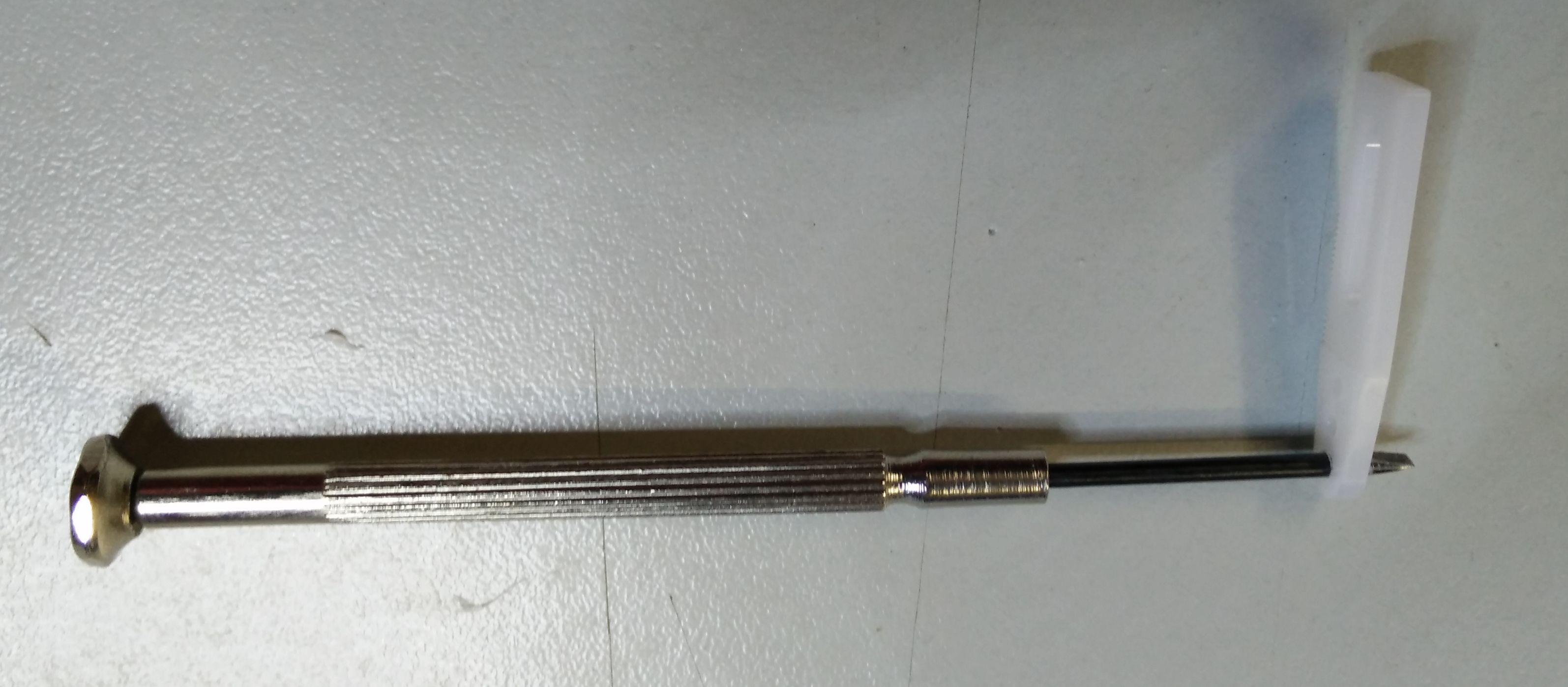
Some hole (where you will need to insert 22m screws) can be too tight. You can widen them by turning a 2mm screwdriver into them.
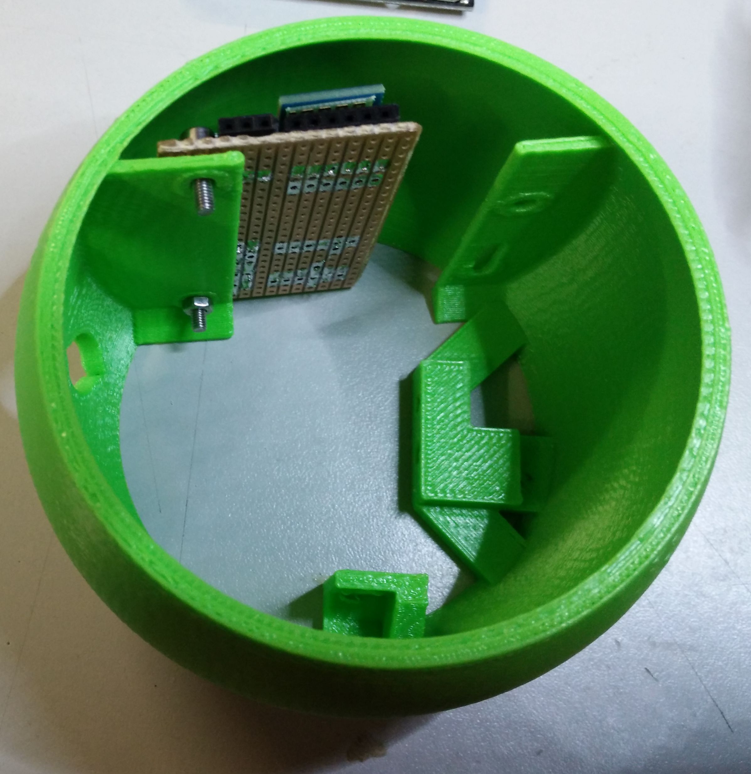
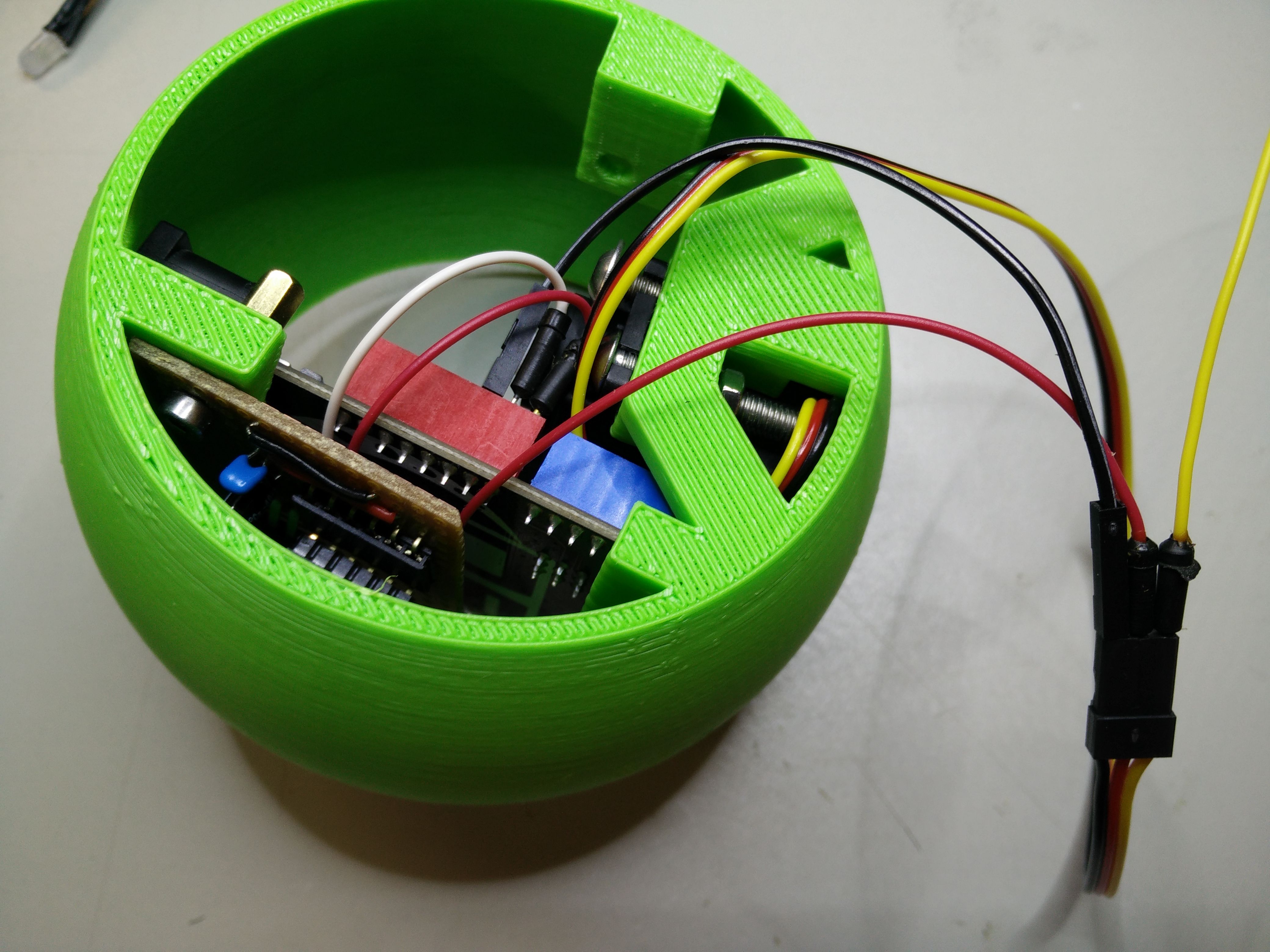
Power an Bluetooth board installation

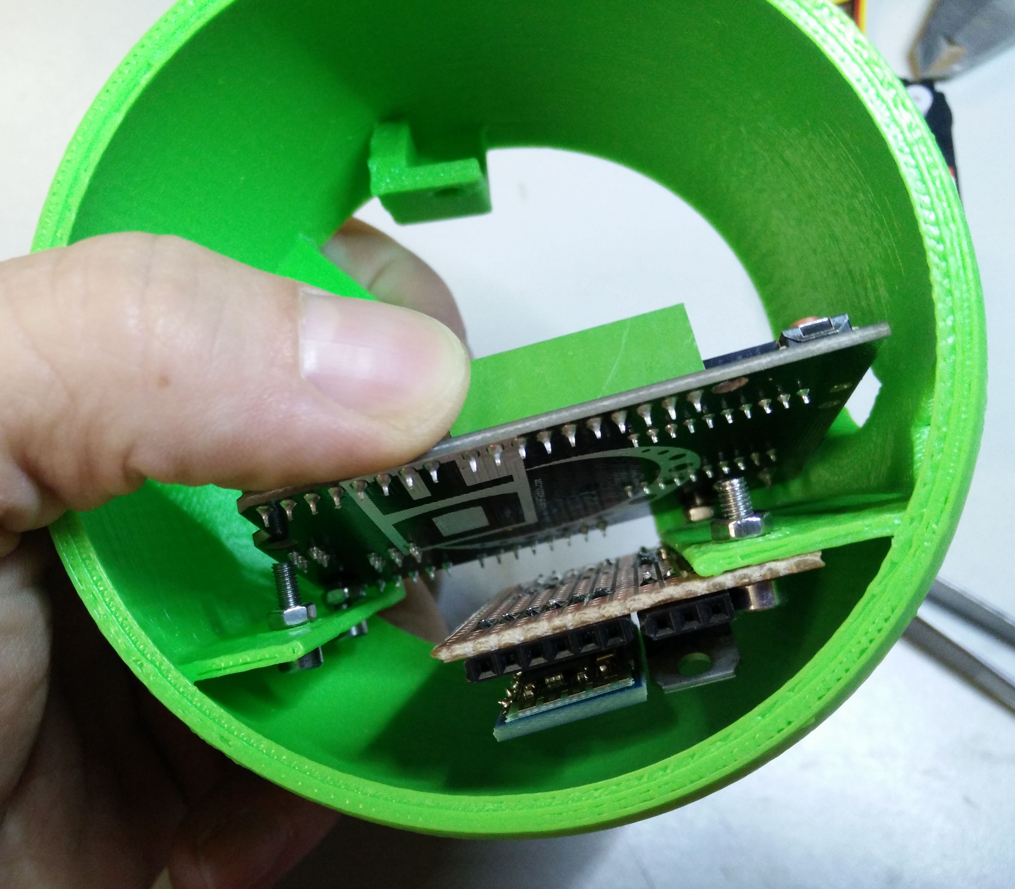
You should start with the bottom screw. First, insert the screw in the board hole the present the board in such a way the the screw enters into its hole in the base.

You will, then have to put a nut on this screw. You can use tweezers like on the left to block the bolt.

You can now insert the second screw from the top with the tweezers then use the same method for the nut.

Use the tweezers to set the 2 others bolts and nuts on the right.
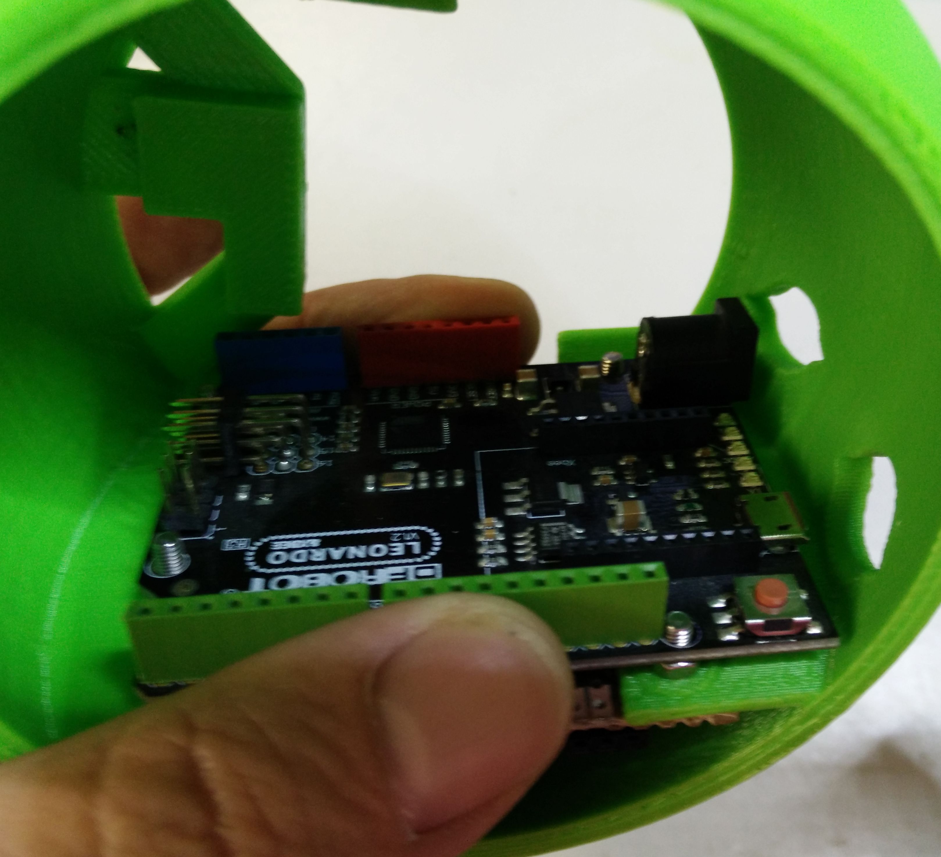
Leonardo board installation

Insert the Leonardo board and present it like that. Fit the 2 bottom holes first.

Then the two others at the top.

To secure the board, it can really be a pain if you try to do it with nuts. I choose to use 10mm spacers and it a lot easier.
On the left the first spacer has been screwed and the board is stabilized.
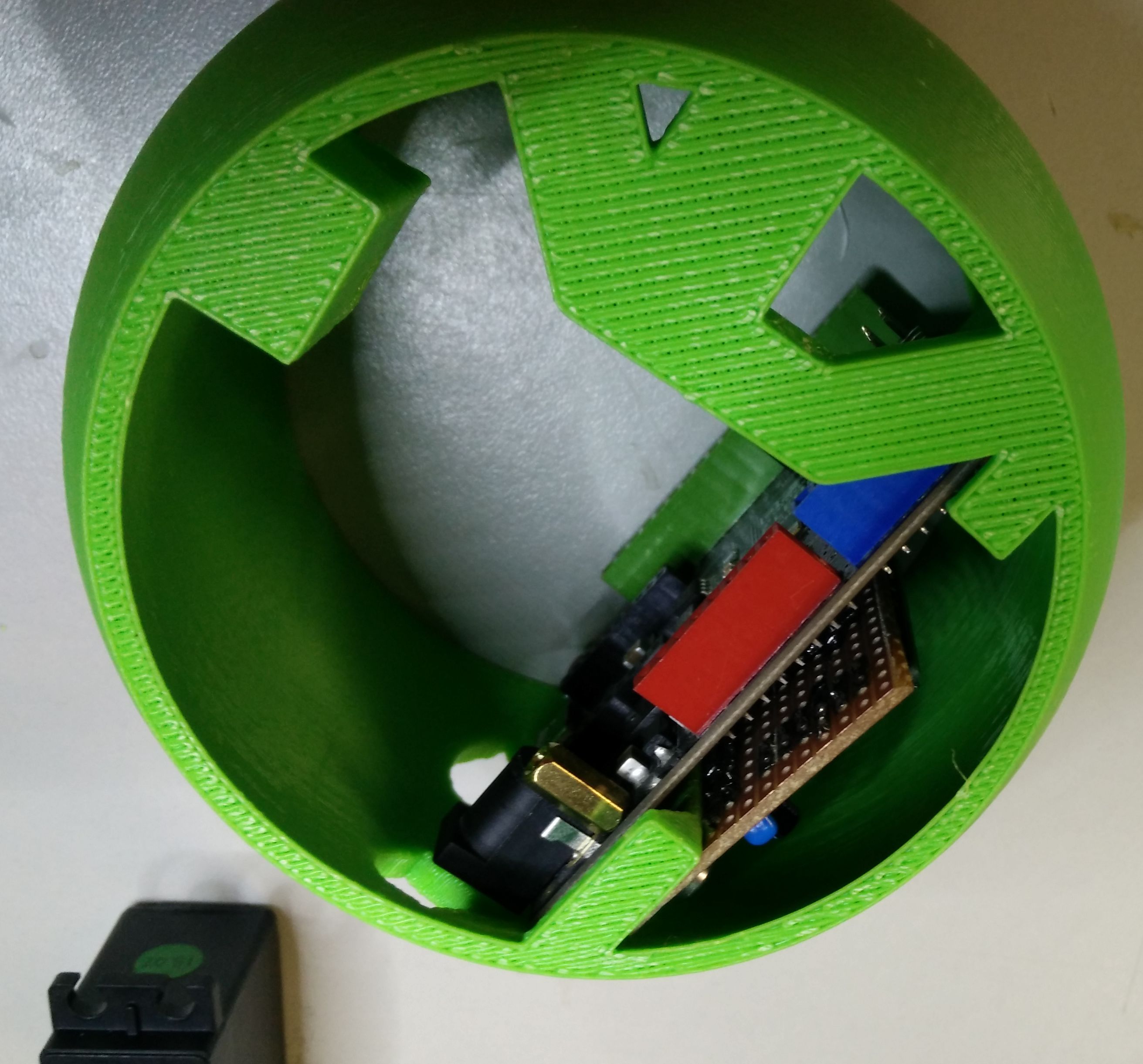
This one is the easier.

The second spacer is tougher and you will need to maintain it with your forefinger from the top of the base, and, from the bottom of the base, make the spacer turn with the flat of a screwdriver to make it turn. Once done, it’s finished with the Leonardo board. There’s no need to try to secure its other corners.
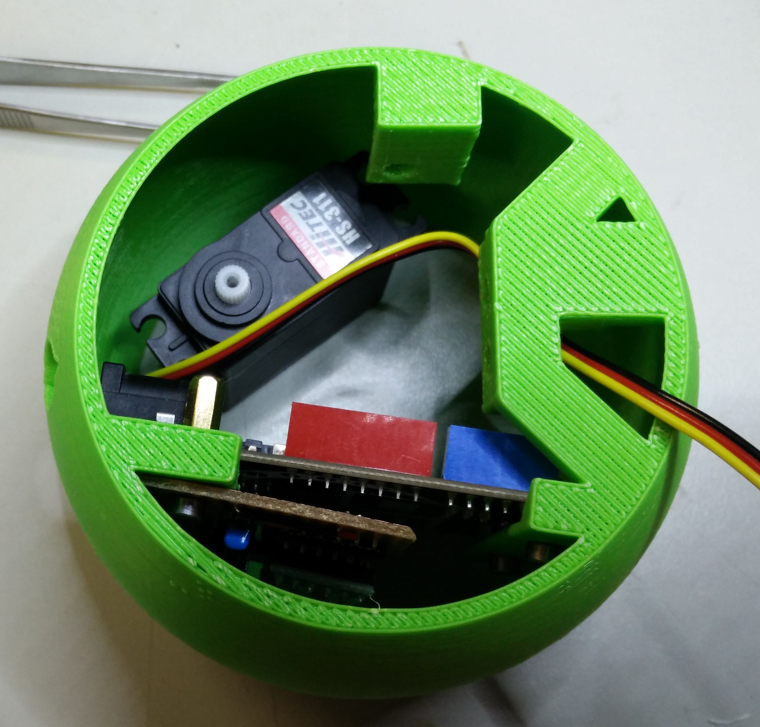
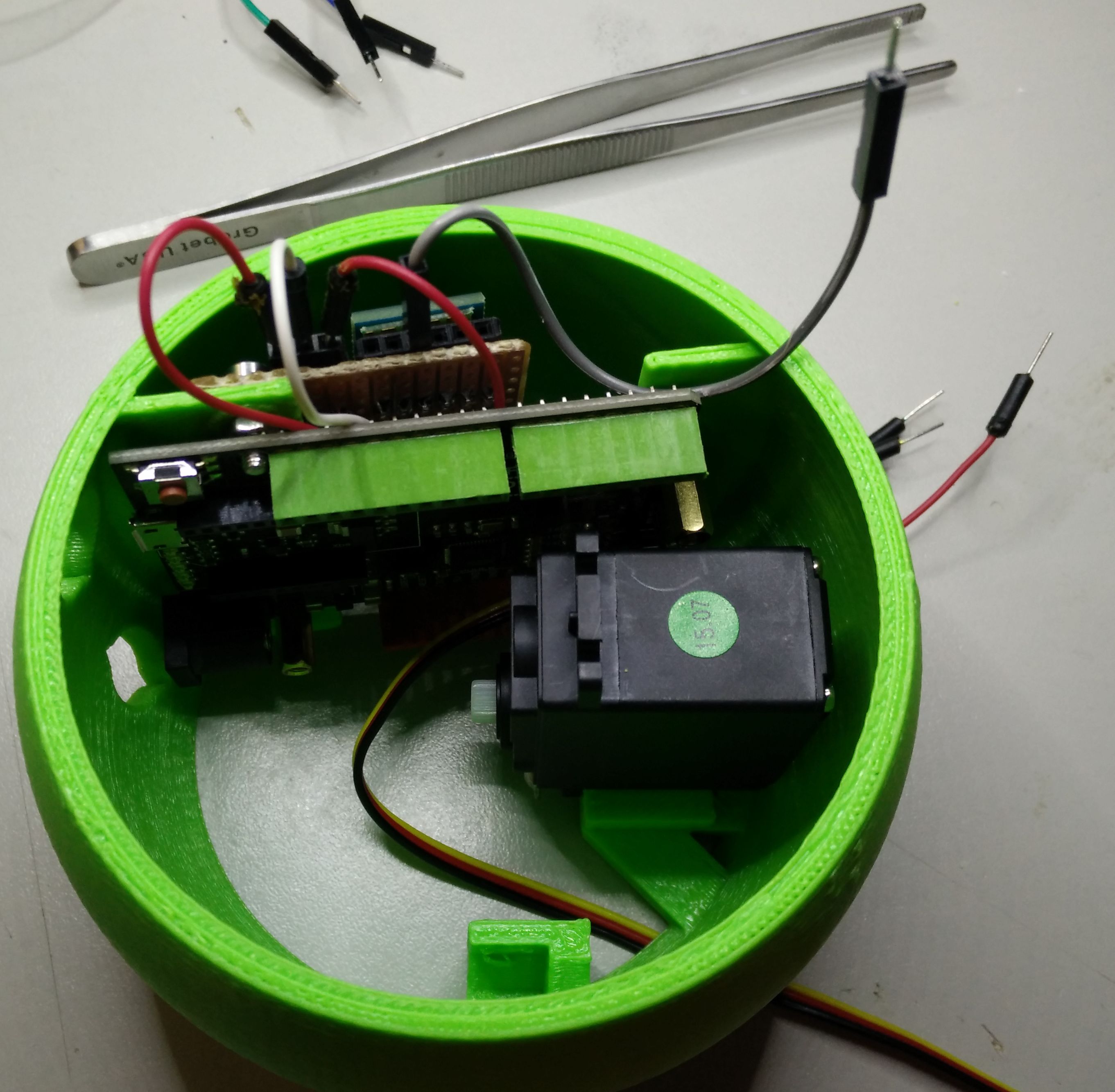
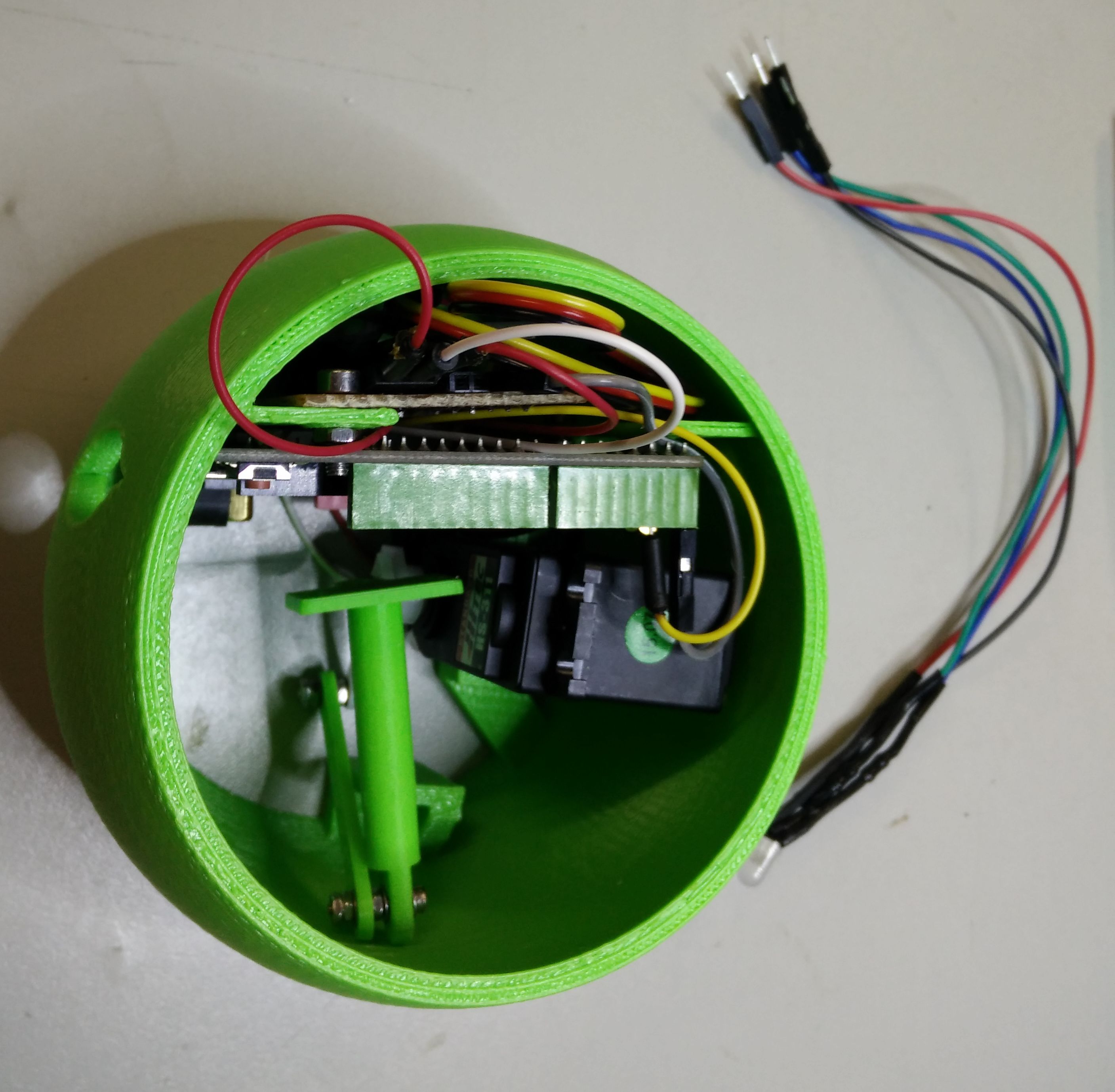
Servo motor installation

Present the motor from the tom and make its cable pass through the bigger hole of the bottom.

Set the first screw and nut as on the left. You will need a 4mm one with more than 16mm length.

Arrange the servo cable like on the left, screw a second m4 screw in the second servo hole. This time you will need a shorter one (10mm). Once done, it’s ok for this step.
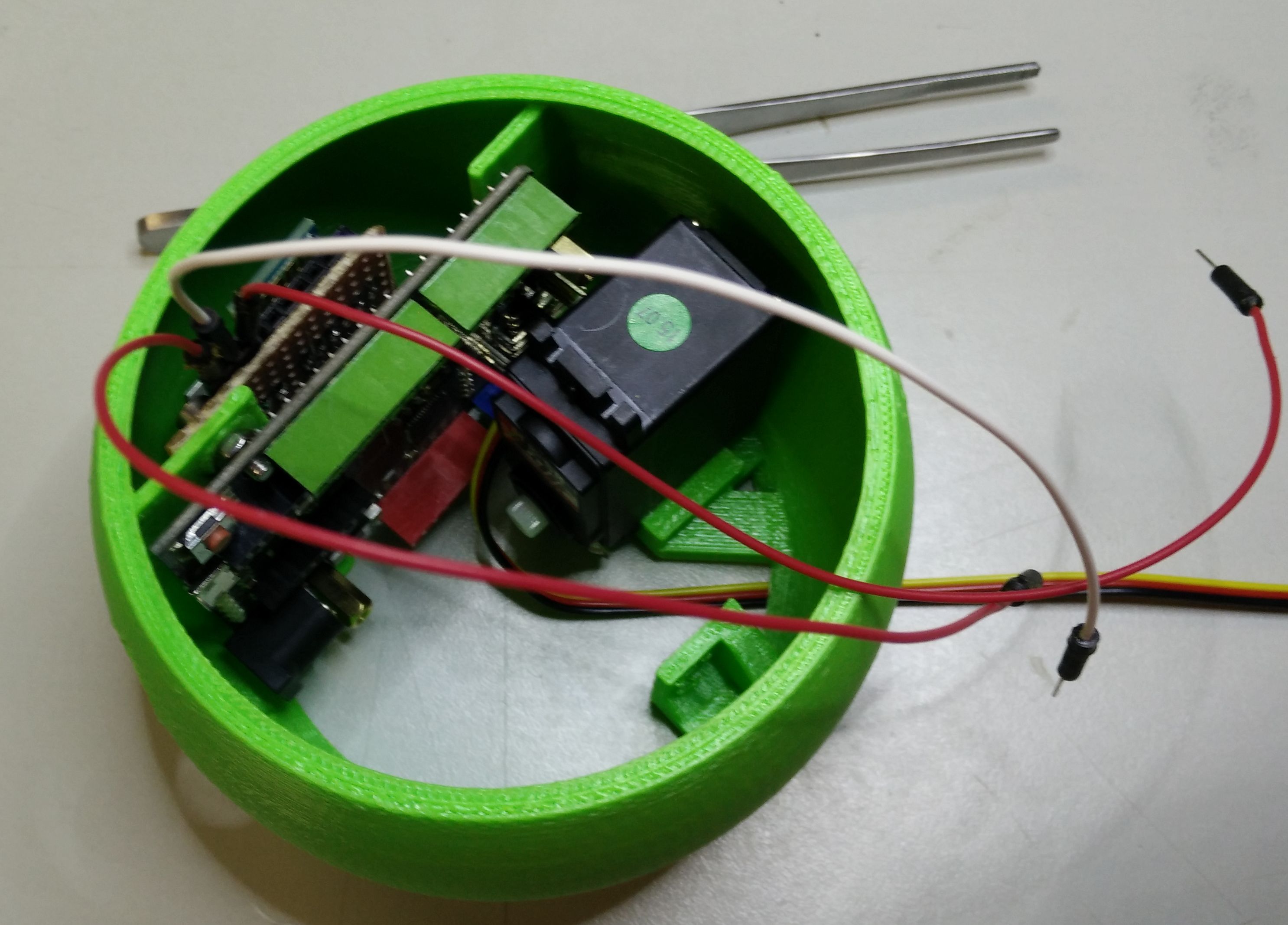
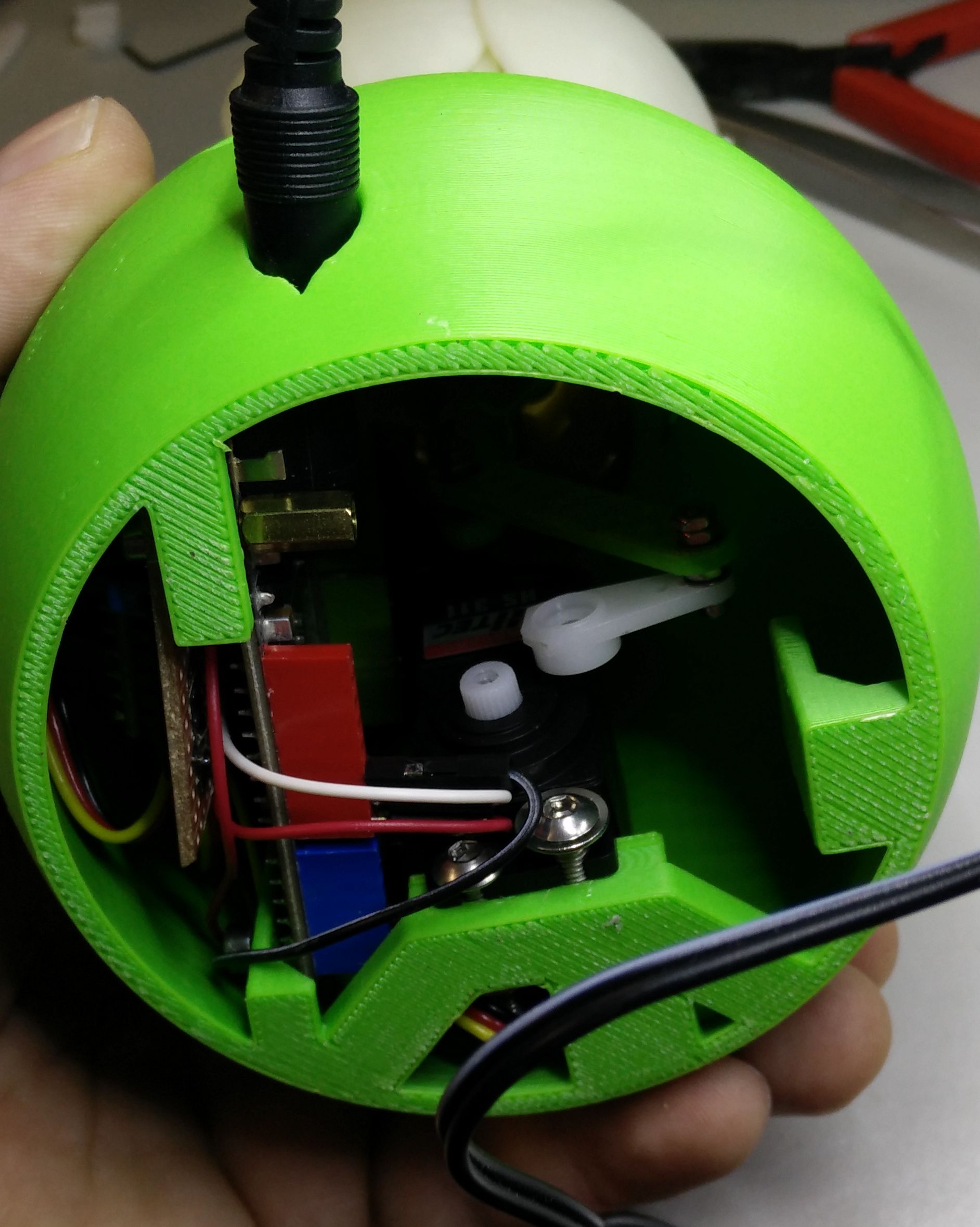
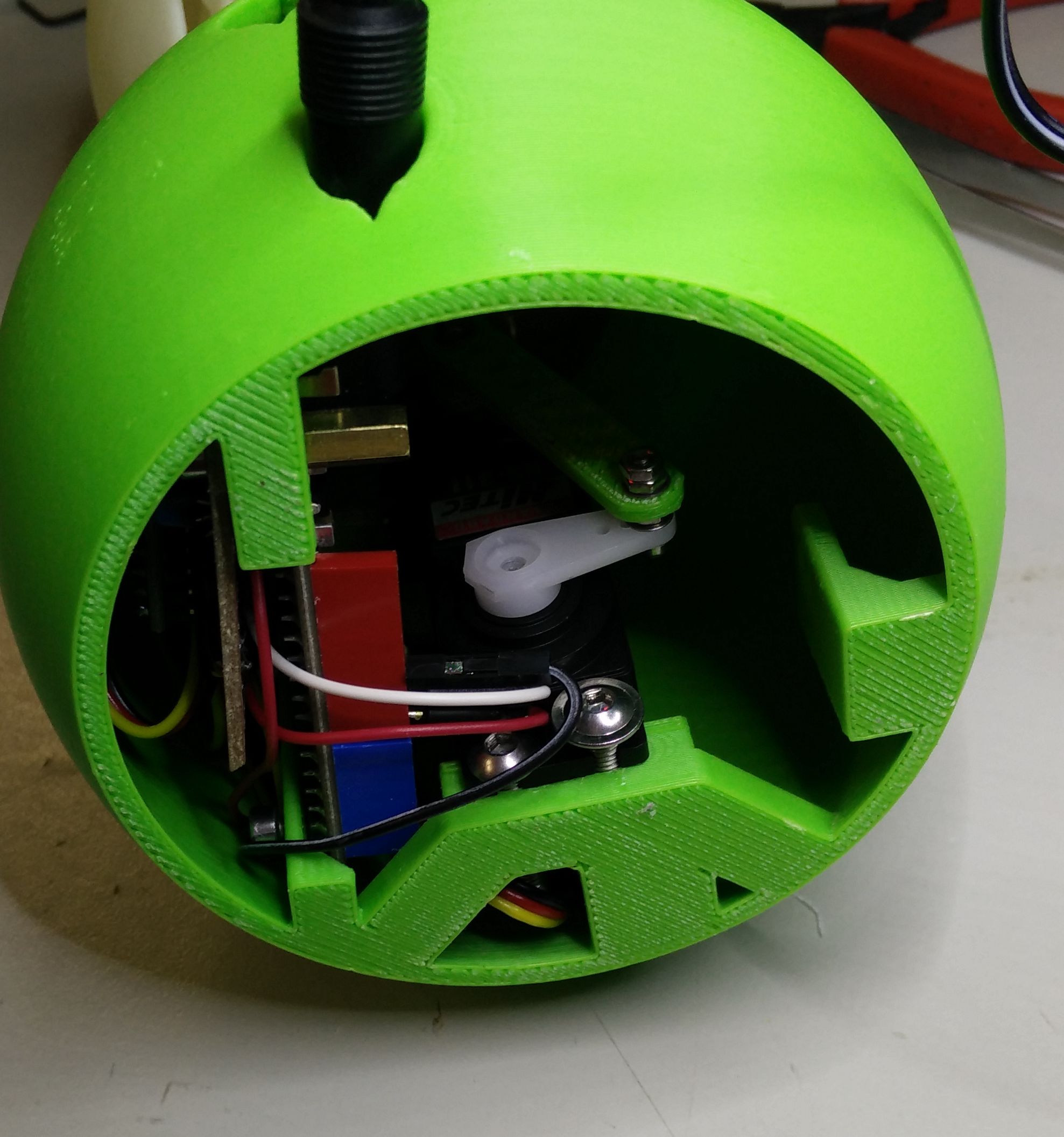
Wiring

Start by plugging on the external board the 3 power jumpers.

Connect Vin and Gnd on Leonardo. Let fly the third jumper (5V output).
Connect with a small jumper, the TX of the HC-05 to the RX of Leonardo.


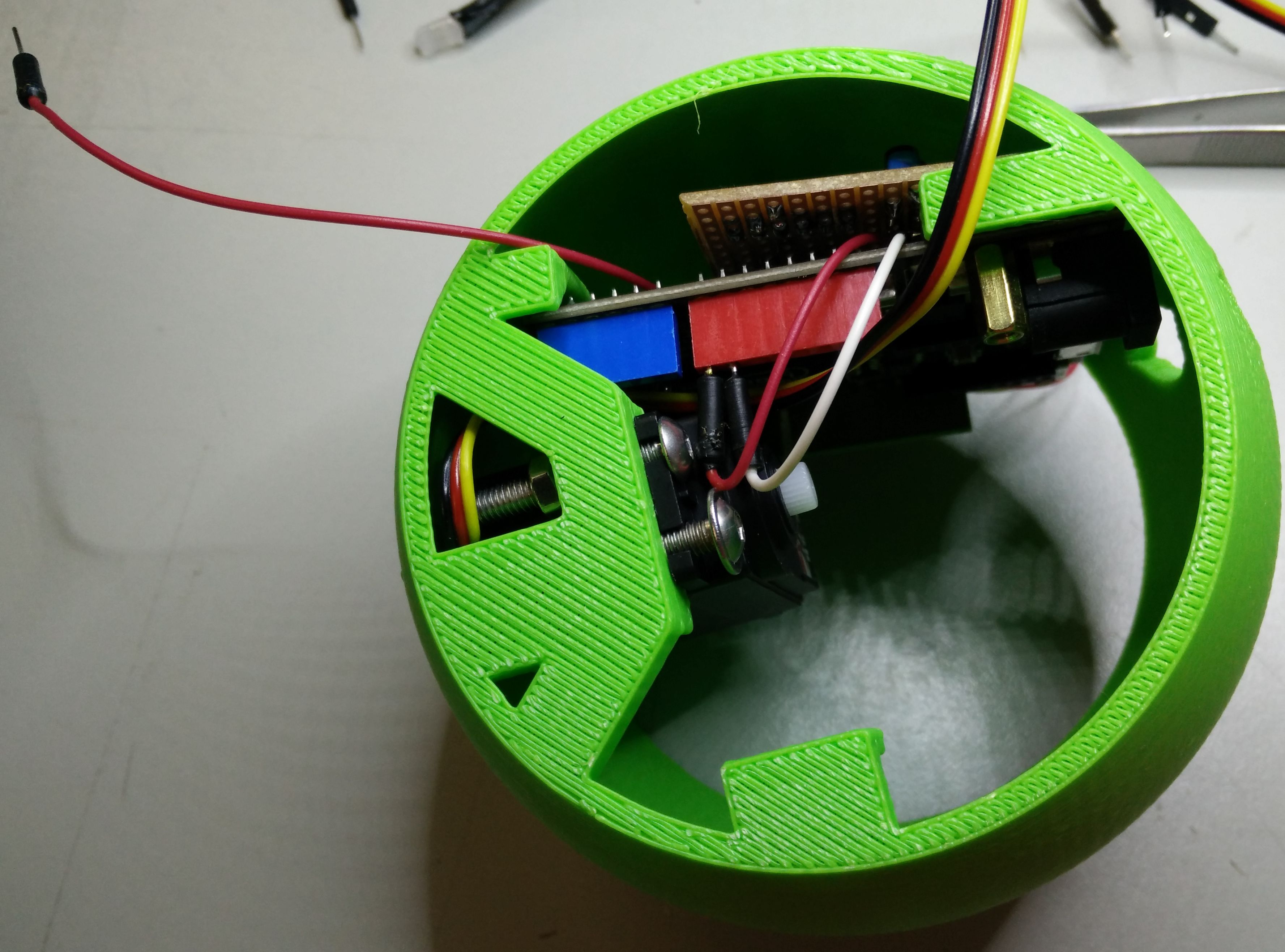
Do some cable management of the servo’s wire. Route it like on the left.

Then plug on it’s header the following :
The external 5v output flying jumper to its 5v pin.
A jumper between its ground to a ground on Leonardo.
A flying jumper to its control pin.

Connect the control pin jumper to pin 2 of Leonardo.

Push the excess length of cable between the external board and the vase.
Before installing the top, you can test if all is working : plug the led pins as on left and power the lamp and try your headset. Led should light and motor spin as you concentrate.
Warning!
After test don’t forget to re-power the board with headset switched off to reset the servo to its 0 position.
Installing the Flower Head

Start to attach the piston to the back of the flower with two 2mmx12 screws, 4 washers and 2 nuts.


Attach a 2mmx12 screw, 2 washers and 1 nut to the bulb.

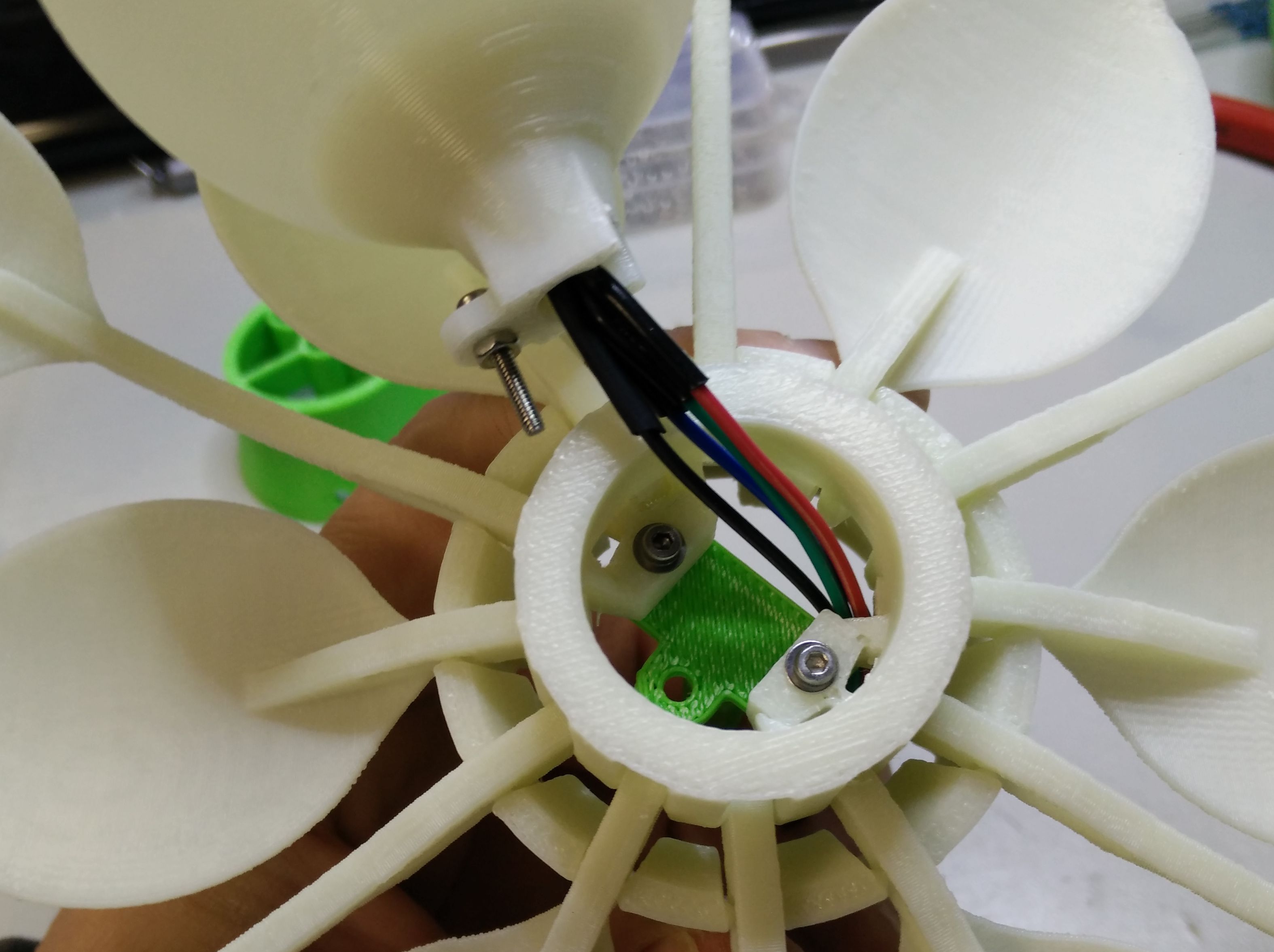
Insert the led into the bulb and its wires into the dedicated hole of the flower.

Screw a nut with washer on the flower screw then insert the led cables into the socket.

Put the socket on the back of the flower.

The holes of the flower and the socket should align.

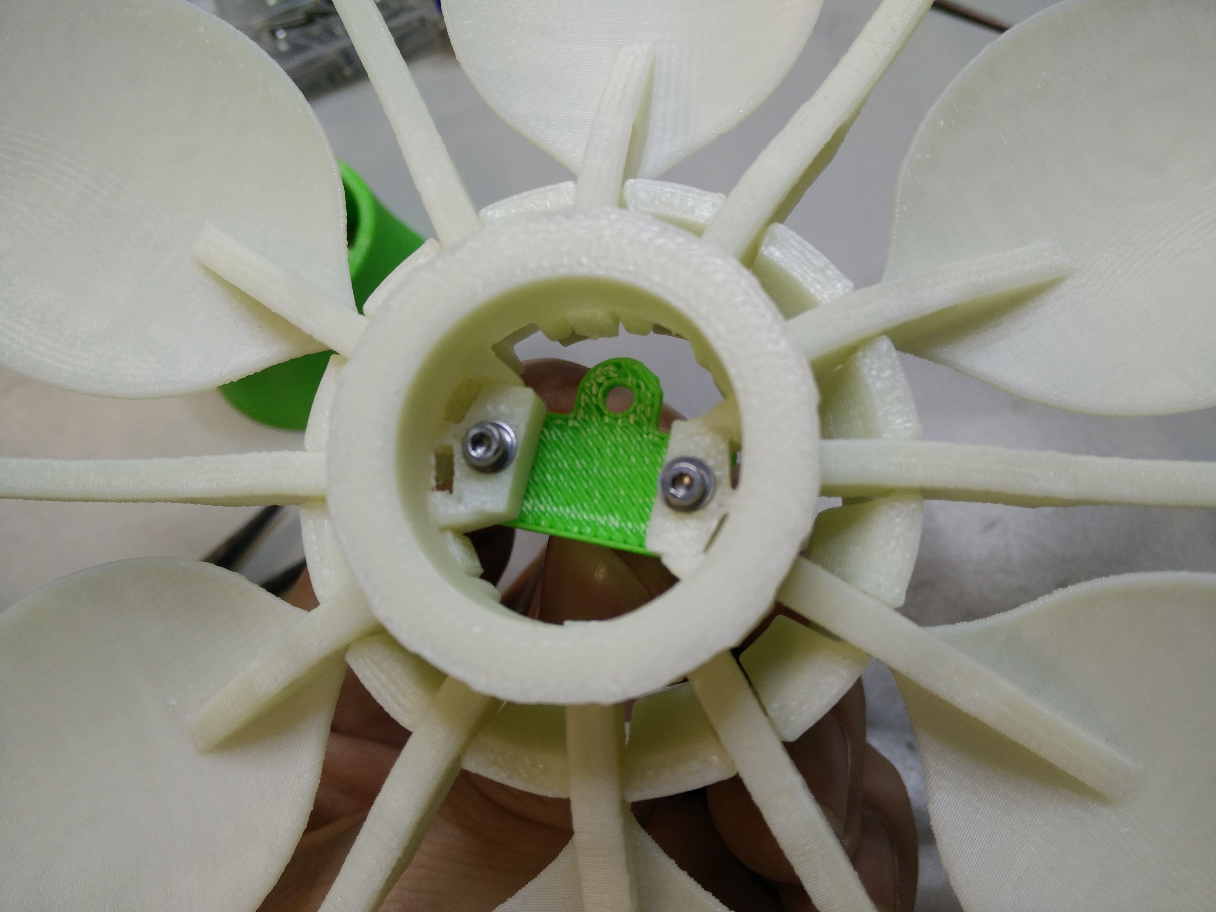
You can verify the all will finish well :
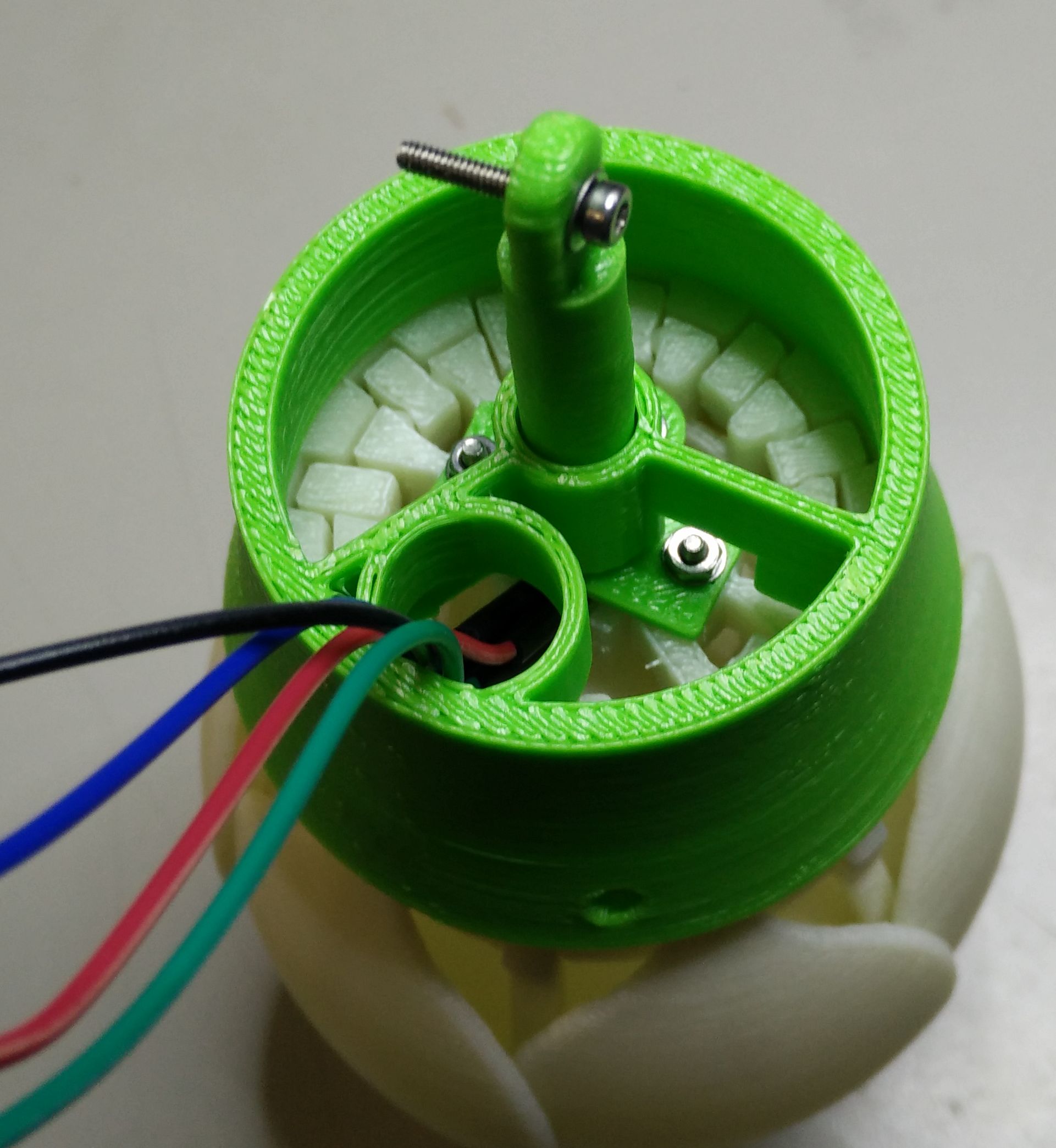
Insert the socket and flower into the base and align the 3 holes (flower, socket and vase).

When you look from the bottom of the vase you should see that the piston is parallel the the face of the servo.
If it the case you can continue.

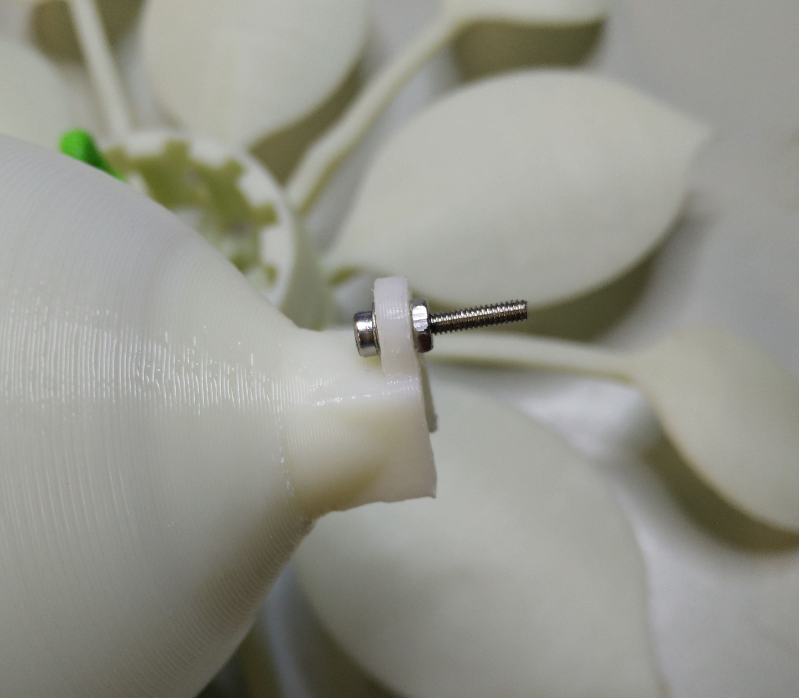
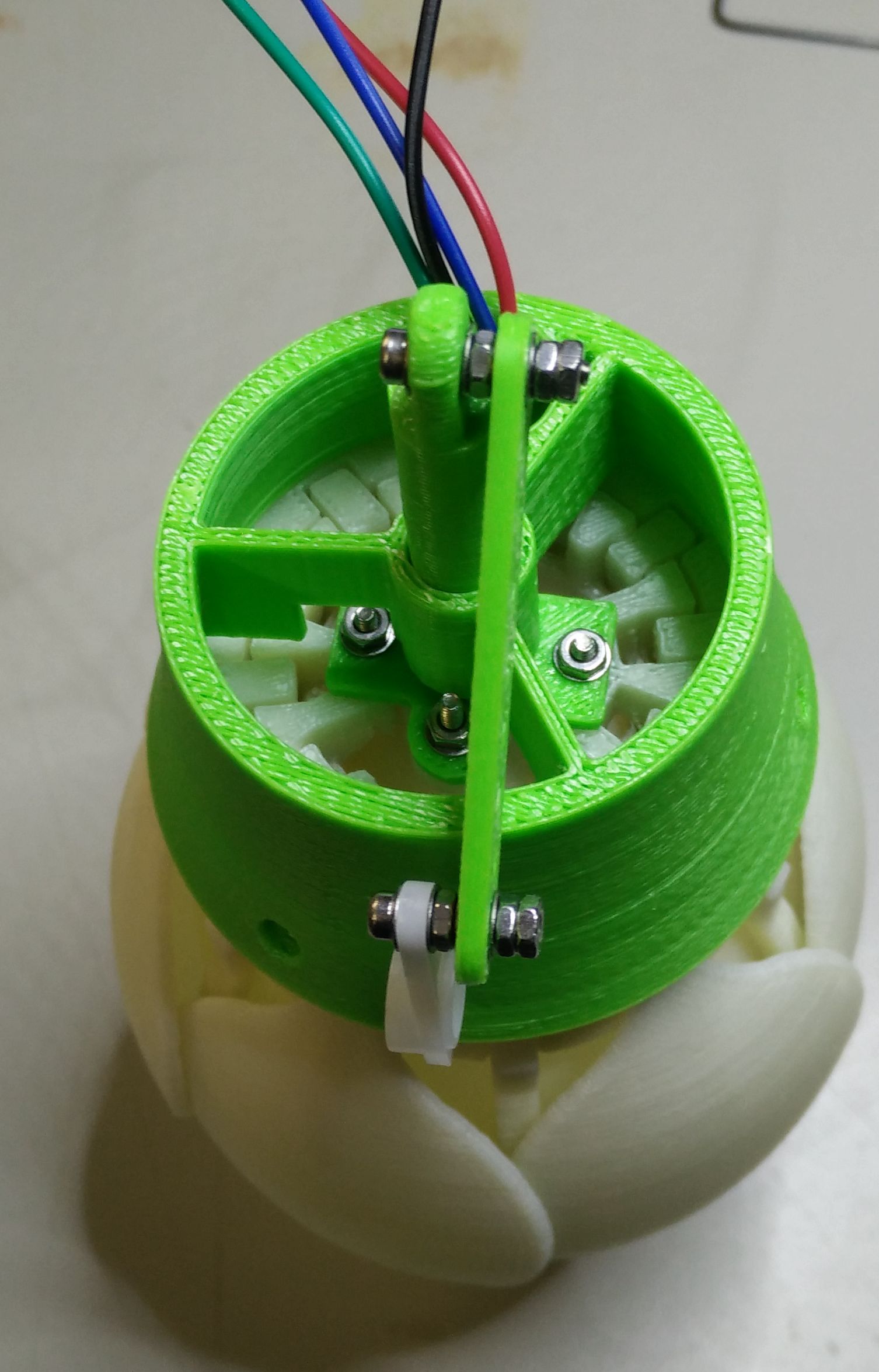
Insert a 2mmx12 screw with a washer into the hole of the piston.

Modify the servo arm with a cutting pliers.

Use washers, nuts and a 2mmx10 screw to mount the arm as on the left.
You’ll have a 12mm screw on the piston and a 10mm on the servo arm.

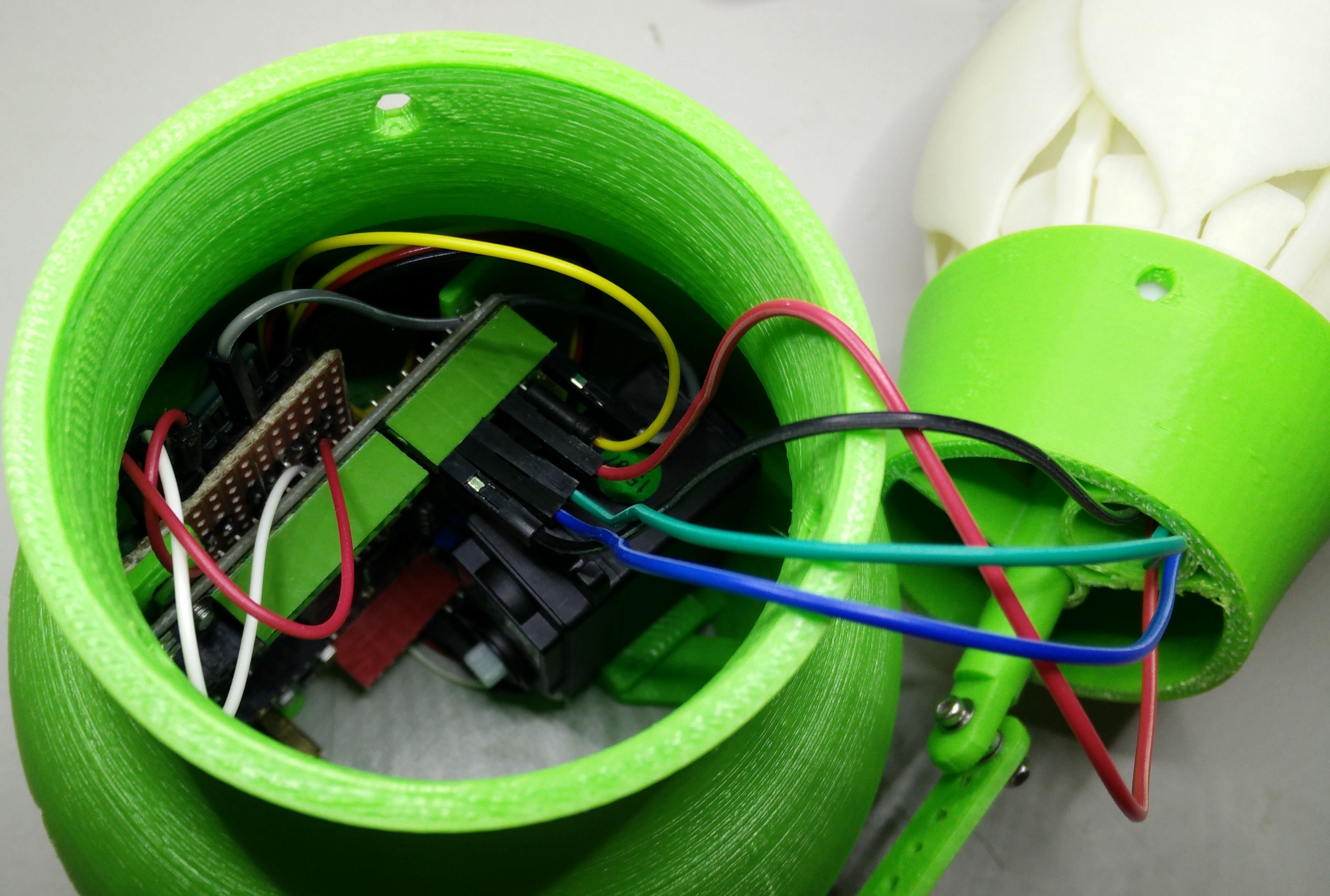
Now you can connect the led pins to the Leonardo.

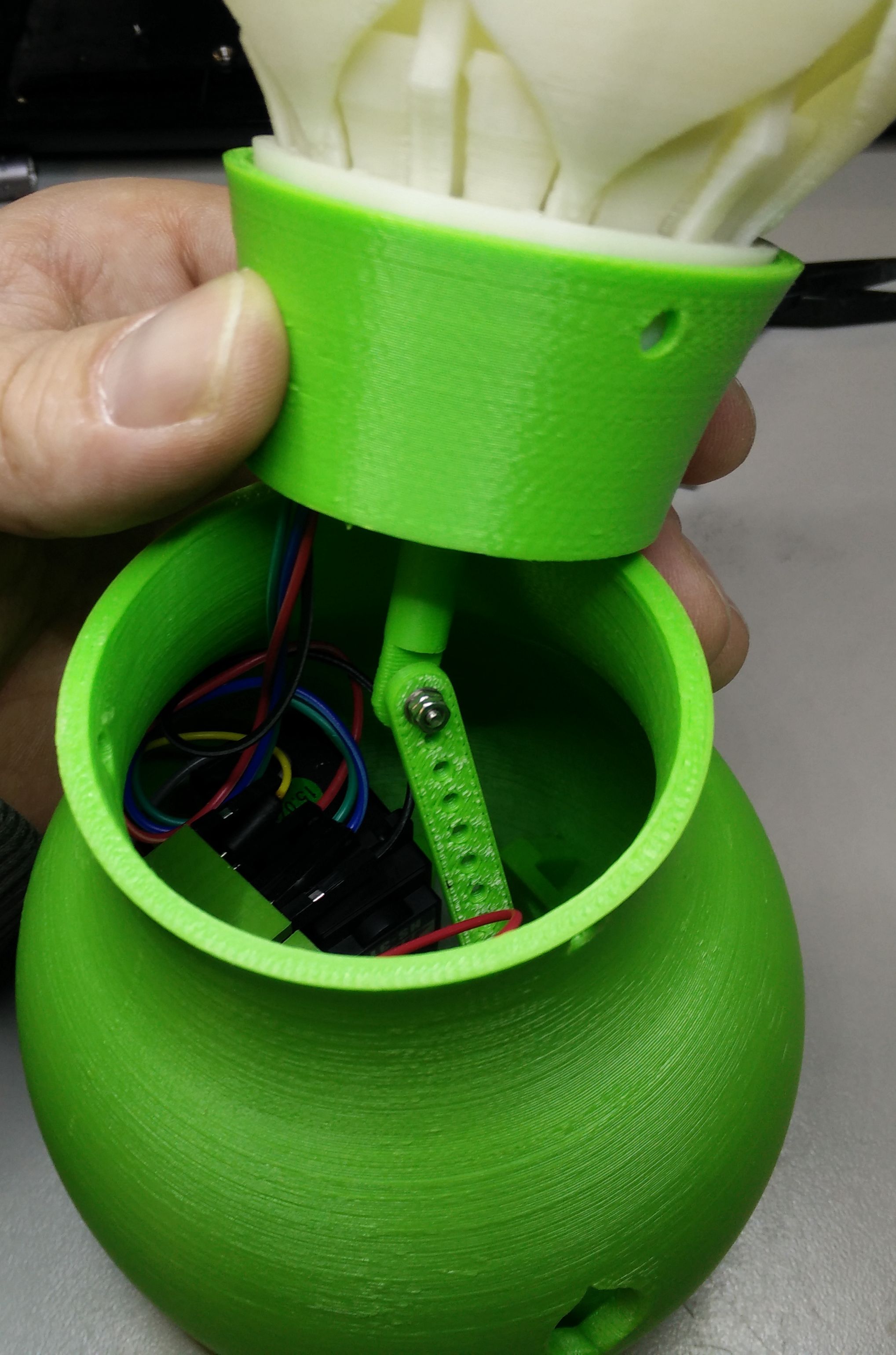
Insert the top into the bottom. Carefully make space with the wires and anticipate that they will not prevent the movement of the piston.

You should now have something like this.
Don’t yet connect the arm on the servo.

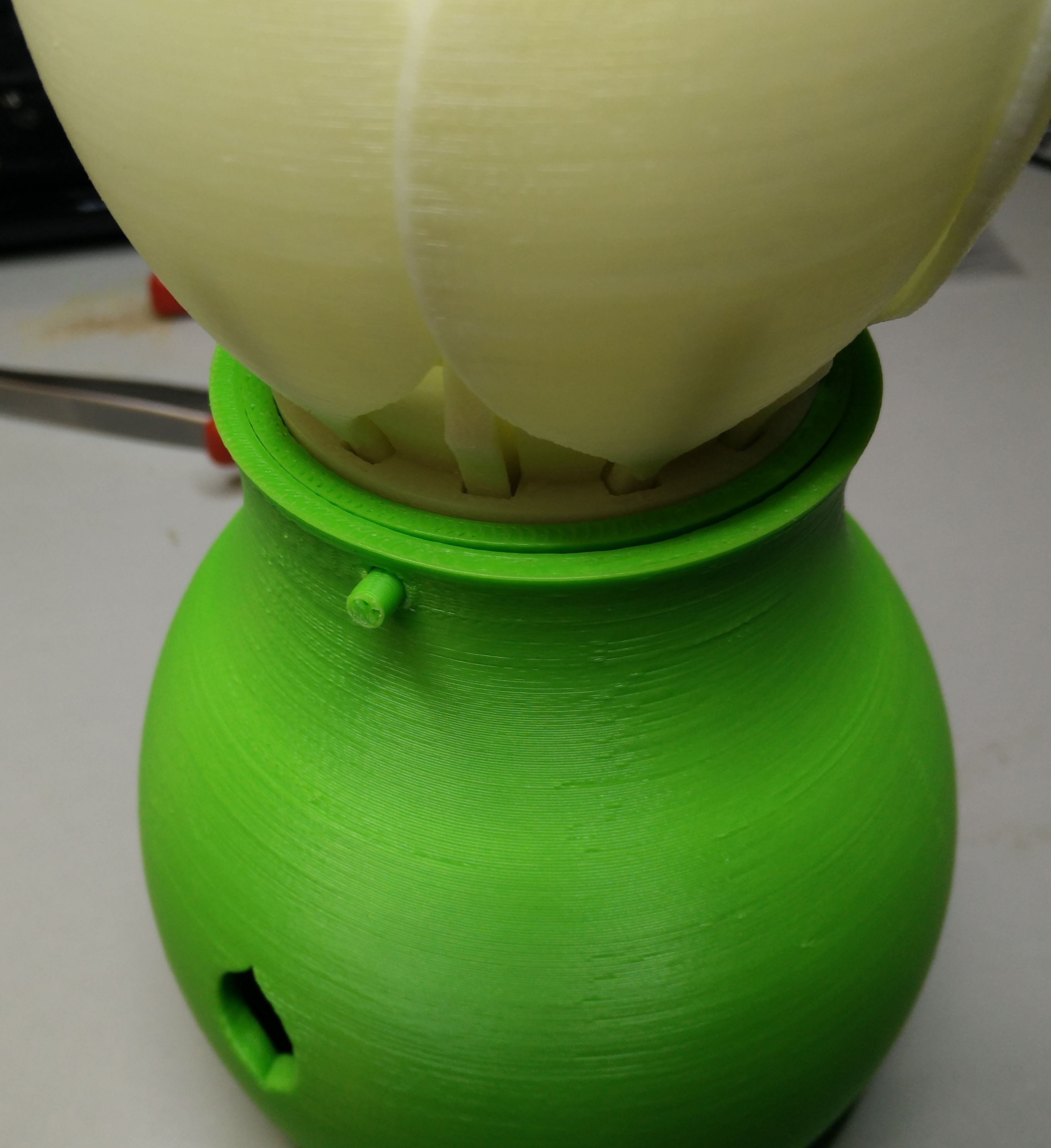
To secure the top on the bottom, you can use 3 pegs and insert them in the 3 holes around the collar. You can also use 3 m4 screws until all is finished and working well.
Nota : if you insert the pegs and you need to unmount the lamp, you can use a needle file : heat it with you soldering iron while push the file in the peg. When the file is 1-2mm in the peg let the file cool and pull.

Power the lamp. The servo will go to its zero position.

plug the arm on the servo.
You’ve finished! You still can add the bottom part if you want.


 The mounting scheme to wire them all :